Morse Tapers and Other Tapers

Dimensions of tapers used in lathe tailstocks, drill press spindles, drill chucks, etc. Cross-checked against the official ISO standard samples, the full public text of the Indian standards, and tool manufacturers' documents.

▦Morse taper quick reference

NumberTaperGauge diameter (mm)Small end diameter, reference (mm)Draw screw
MT01:19.212[1][2][3]9.045[1][2][4]6.4[1][2]—[1]1 source · reference
MT11:20.047[1][2]12.065[1][2][5]9.4[1][2]M6 (inch products: UNC 1/4)[1][2][5]
MT21:20.020[1][2][3]17.78[1][2][5]14.6[1][2]M10 (inch products: UNC 3/8)[1][2][5]
MT31:19.922[1][2][3]23.825[1][2][5]19.8[1][2]M12 (inch products: UNC 1/2)[1][2][5]
MT41:19.254[1][2][3]31.267[1][2][5]25.9[1][2]M16 (inch products: UNC 5/8)[1][2][5]
MT51:19.002[1][2][3]44.399[1][2][5]37.6[1][2]M20 (inch products: UNC 5/8)[1][2][5]
MT61:19.180[1][2][3]63.348[1][2][5]53.9[1][2]M24 (inch products: UNC 1)[1][2][5]
MT7—Not confirmed in public sources—Not confirmed in public sources——Not confirmed in public sources

The taper ratio differs slightly for each Morse taper number (about 1/20). MT7 is not included in ISO 296.

Taper shape and taper ratio (cross-sections at the same scale)
Morse taper (MT3, with tang)Gauge diameter positionDdLTangMT3: taper 1 : 19.922Half-angle 1°26′16″D = 23.825 mmThe angle is small, so when pushed in,friction holds it in place (self-holding)Taper ratio = (D − d) ÷ L MT is about 1/20: the diameter shrinks by 1 over a length of 207/24 taper (NT40 example; BT and CAT use the same taper)Draw screw (M16)Half-angle 8°18′D1L7/24: the diameter changes by 7 for every 24 of L(1 : 3.43) Half-angle 8°18′, included angle about 16°36′NT40 D1 = 44.45 mmThe angle is large and does not self-hold, soit is drawn in with a draw screw or pull stud

Both are drawn at the same scale, with the taper angles per the standard values (L of MT3 is the maximum l1 of 81 mm; the length of the 7/24 taper section is a rough guide above the drawing). Taper ratio is expressed as the difference in diameters ÷ length, using diameters rather than the half-angle.

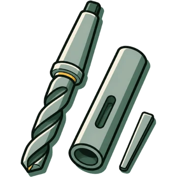
Morse taper (MT)

Illustration: Morse taper (MT)
Illustration (not an exact drawing)

MT0ISO 296, IS 1715, DIN 228

Taper
1:19.212[1][2][3]= 0.6246:12 (0.05205). The ISO 1119 taper angle (included angle) is 2°58′53.8″
Taper half-angle
1°29′27″[2]1 source · reference
Gauge diameter (mm)
9.045[1][2][4]TAC's MT0 column says Contact us, with no value
Small end diameter, reference (mm)
6.4[1][2]d (reference value)
Length
l1 max 50 / l3 56.5 (symbols as in the ISO 296 table)[1][2]
Draw screw
—[1]1 source · referenceIn ISO 296, the thread column for MT0 is "—" (not specified)
Tang
Tang thickness b(h13) = 3.9, e max 10.5[1]1 source · reference
Size
MT0
There is no MT0 in the inch table (ISO 296 Table 3)

MT1ISO 296, IS 1715, DIN 228, ASME B5.10

Taper
1:20.047[1][2]=0.59858:12 (0.04988)
Taper half-angle
1°25′43″[2]1 source · reference
Gauge diameter (mm)
12.065[1][2][5]Inch notation D = 0.475 in (ISO 296 Table 3)
Small end diameter, reference (mm)
9.4[1][2]
Length
l1 max 53.5 / l3 62[1][2][5]
Draw screw
M6 (inch products: UNC 1/4)[1][2][5]TAC gives M6x1
Tang
b=5.2, e max 13.5[1]1 source · reference
Size
MT1

MT2ISO 296, IS 1715, DIN 228, ASME B5.10

Taper
1:20.020[1][2][3]ISO 296 writes "1:20,02". Included angle 2°51′40.8″ (ISO 1119)
Taper half-angle
1°25′50″[2]1 source · reference
Gauge diameter (mm)
17.78[1][2][5]0.700 in
Small end diameter, reference (mm)
14.6[1][2]
Length
l1 max 64 / l3 75[1][2][5]
Draw screw
M10 (inch products: UNC 3/8)[1][2][5]
Tang
b=6.3, e max 16[1]1 source · reference
Size
MT2

MT3ISO 296, IS 1715, DIN 228, ASME B5.10

Taper
1:19.922[1][2][3]Included angle 2°52′31.4″
Taper half-angle
1°26′16″[2]1 source · reference
Gauge diameter (mm)
23.825[1][2][5]0.938 in
Small end diameter, reference (mm)
19.8[1][2]
Length
l1 max 81 / l3 94[1][2][5]
Draw screw
M12 (inch products: UNC 1/2)[1][2][5]
Tang
b=7.9, e max 20[1]1 source · reference
Size
MT3

MT4ISO 296, IS 1715, DIN 228, ASME B5.10

Taper
1:19.254[1][2][3]Included angle 2°58′30.4″
Taper half-angle
1°29′15″[2]1 source · reference
Gauge diameter (mm)
31.267[1][2][5]1.231 in
Small end diameter, reference (mm)
25.9[1][2]
Length
l1 max 102.5 / l3 117.5[1][2][5]
Draw screw
M16 (inch products: UNC 5/8)[1][2][5]
Tang
b=11.9, e max 24[1]1 source · reference
Size
MT4

MT5ISO 296, IS 1715, DIN 228, ASME B5.10

Taper
1:19.002[1][2][3]Included angle 3°0′52.4″
Taper half-angle
1°30′26″[2]1 source · reference
Gauge diameter (mm)
44.399[1][2][5]1.748 in
Small end diameter, reference (mm)
37.6[1][2]
Length
l1 max 129.5 / l3 149.5[1][2][5]
Draw screw
M20 (inch products: UNC 5/8)[1][2][5]Inch products use the same UNC 5/8 as MT4
Tang
b=15.9, e max 29[1]1 source · reference
Size
MT5

MT6ISO 296, IS 1715, DIN 228, ASME B5.10

Taper
1:19.180[1][2][3]Included angle 2°59′11.7″
Taper half-angle
1°29′36″[2]1 source · reference
Gauge diameter (mm)
63.348[1][2][5]2.494 in
Small end diameter, reference (mm)
53.9[1][2]
Length
l1 max 182 / l3 210[1][2][5]
Draw screw
M24 (inch products: UNC 1)[1][2][5]
Tang
b=19, e max 40[1]1 source · reference
Size
MT6

MT7ASME B5.10 (reportedly)

Taper
—Not confirmed in public sourcesISO 296 and IS 1715 cover only MT0–6. The values 1:19.231 and D = 83.058 mm were found only on shop and aggregator sites and in search summaries, which cannot be cited as sources
Gauge diameter (mm)
—Not confirmed in public sourcesSame as above
Draw screw
—Not confirmed in public sources
Size
MT7
The text of ASME B5.10 could not be obtained

Metric taper (ME)

ME4ISO 296, IS 1715, DIN 228

Taper
1:20[1][2]Half angle 1°25′56″ (IS 1715)
Gauge diameter (mm)
4[1][2]d≈2.9, l1 max 23, l2 max 25
Draw screw
—[1]1 source · referenceThread and tang not specified (—)
Size
ME4

ME6ISO 296, IS 1715, DIN 228

Taper
1:20[1][2]
Gauge diameter (mm)
6[1][2]d≈4.4, l1 max 32, l2 max 35
Draw screw
—[1]1 source · referenceNot specified
Size
ME6

ME80ISO 296, IS 1715, DIN 228

Taper
1:20[1][2]
Gauge diameter (mm)
80[1][2]d≈70.2, l1 max 196, l3 220
Draw screw
M30[1][2]
Tang
b=26, e max 48[1]1 source · reference
Size
ME80

ME100ISO 296, IS 1715, DIN 228

Taper
1:20[1][2]
Gauge diameter (mm)
100[1][2]d≈88.4, l1 max 232, l3 260
Draw screw
M36[1][2]
Tang
b=32, e max 58[1]1 source · reference
Size
ME100

ME120ISO 296, IS 1715, DIN 228

Taper
1:20[1][2]
Gauge diameter (mm)
120[1][2]d≈106.6, l1 max 268, l3 300
Draw screw
M36[1][2]
Tang
b=38, e max 68[1]1 source · reference
Size
ME120

ME160ISO 296, IS 1715, DIN 228

Taper
1:20[1][2]
Gauge diameter (mm)
160[1][2]d≈143, l1 max 340, l3 380
Draw screw
M48[1][2]
Tang
b=50, e max 88[1]1 source · reference
Size
ME160

ME200ISO 296, IS 1715, DIN 228

Taper
1:20[1][2]
Gauge diameter (mm)
200[1][2]d≈179.4, l1 max 412, l3 460
Draw screw
M48[1][2]
Tang
b=62, e max 108[1]1 source · reference
Size
ME200

Brown & Sharpe taper (B&S)

B&S 1ISO 296 Table 3

Taper
1:23.904 (=0.502:12, approx. 0.502 in/ft)[1]1 source · referenceCorresponds to the commonly cited "approx. 0.5 in/ft". Only B&S No.1–3 appear in ISO 296
Gauge diameter (inch)
0.23922[1]1 source · referencemm conversion 6.076 (calculated). D1≈0.24314, d≈0.2, l1 max 15/16 in
Size
B&S 1

B&S 2ISO 296 Table 3

Taper
1:23.904[1]1 source · reference
Gauge diameter (inch)
0.29968[1]1 source · reference≈7.612 mm (calculated). d≈0.25, l1 max 1 3/16 in
Size
B&S 2

B&S 3ISO 296 Table 3

Taper
1:23.904[1]1 source · reference
Gauge diameter (inch)
0.37525[1]1 source · reference≈9.531 mm (calculated). d≈0.3125, l1 max 1 1/2 in
Size
B&S 3
No source that can be cited was found for No.4 and above

Jacobs taper (JT)

JT0ISO 239, IS 2243

Large end diameter (mm)
6.35[6][7]
Small end diameter (mm)
5.802[6][7]Calculated value (reference)
Length (mm)
11.112[6][7]IS 2243 gives 11.11
Diametral taper
  • ISO 239:1999:0.04929[6]
  • IS 2243:1971:0.04928[7]
1 source · referenceDiffers at the 5th digit
Size
JT0

JT1ISO 239, IS 2243

Large end diameter (mm)
9.754[6][7]
Small end diameter (mm)
8.469[6][7]
Length (mm)
16.669[6][7]IS gives 16.67
Diametral taper
0.07709 (=1:12.972, included angle 4°24′52.9″)[6][7][3]
Size
JT1

JT2SISO 239 (J2s), IS 2243 (2 short)

Large end diameter (mm)
13.94[6][7]
Small end diameter (mm)
12.386[6][7]
Length (mm)
19.05[6][7]
Diametral taper
0.08155 (same as JT2)[6][7]
Size
JT2S
ISO 239 calls it "J2s"

JT2ISO 239, IS 2243

Large end diameter (mm)
14.199[6][7]
Small end diameter (mm)
12.386[6][7]
Length (mm)
22.225[6][7]IS gives 22.22
Diametral taper
0.08155 (=1:12.262, included angle 4°40′12.2″)[6][7][3]
Size
JT2

JT33ISO 239, IS 2243

Large end diameter (mm)
15.85[6][7]
Small end diameter (mm)
14.237[6][7]
Length (mm)
25.4[6][7]
Diametral taper
0.0635 (=1:15.748, included angle 3°38′13.4″)[6][7][3]IS 2243 gives 0.06349. Only a rounding difference
Size
JT33

JT6ISO 239, IS 2243

Large end diameter (mm)
17.17[6][7]
Small end diameter (mm)
15.852[6][7]
Length (mm)
25.4[6][7]
Diametral taper
0.05191 (=1:19.264, included angle 2°58′24.9″)[6][7][3]
Size
JT6

JT3ISO 239, IS 2243

Large end diameter (mm)
20.599[6][7]
Small end diameter (mm)
18.951[6][7]
Length (mm)
30.956[6][7]IS gives 30.96
Diametral taper
0.05325 (=1:18.779, included angle 3°3′1.2″)[6][7][3]
Size
JT3
Shown in parentheses in ISO 239 (size to be avoided where possible)

JT4ISO 239, IS 2243

Large end diameter (mm)
28.55[6][7]
Small end diameter (mm)
26.346[6][7]
Length (mm)
42.069[6][7]
Diametral taper
0.0524[6][7]
Size
JT4
Both standards say "avoid where possible"

JT5ISO 239, IS 2243

Large end diameter (mm)
35.89[6][7]
Small end diameter (mm)
33.422[6][7]
Length (mm)
47.625[6][7]IS gives 47.62
Diametral taper
0.05183[6][7]
Size
JT5
Size to be avoided where possible

7/24 (National / NT)

CommonISO 297, ISO 1119

Taper
7:24 (=1:3.4285714, taper on diameter 0.29167)[8][3]1 source · referenceMedium, since both are published by ISO
Taper half-angle
8°17′49.7″ (rounded to 8°17′50″)[3]1 source · referenceIncluded angle divided by 2. Agrees with HAIMER's 8°17′50″
Included angle (full angle)
16°35′39.4443″ (=16.594290°)[3]1 source · referenceAlso agrees with the calculation atan(7/48)×2
Size
Common
As its title says, ISO 297 is for "manual change". It lists a method of pulling in with a draw bolt (draw bar) screwed in from the rear, and a method of holding the collar from the front

NT30 (ISO 297 No.30)ISO 297

Gauge diameter (mm)
31.75[8]1 source · referenceD1 = reference diameter at the gauge plane. The table has length columns of 68.4 and 48.4
Draw screw
M12 (UN products: 0.500-13)[8]1 source · reference
Size
NT30 (ISO 297 No.30)
Treating NT30 as ISO 297 No.30 was the researcher's judgment

NT40 (ISO 297 No.40)ISO 297

Gauge diameter (mm)
44.45[8]1 source · referenceThe table has length columns of 93.4 and 65.4
Draw screw
M16 (UN products: 0.625-11)[8]1 source · reference
Size
NT40 (ISO 297 No.40)

No.45ISO 297

Gauge diameter (mm)
57.15[8]1 source · reference
Draw screw
M20 (UN products: 0.75-10)[8]1 source · reference
Size
No.45

NT50 (ISO 297 No.50)ISO 297

Gauge diameter (mm)
69.85[8]1 source · reference
Draw screw
M24 (UN products: 1.000-8)[8]1 source · reference
Size
NT50 (ISO 297 No.50)
No.55–80 also exist: D1 is 88.9/107.95/133.35/165.1/203.2/254, threads M24/M30/M36/M36/M48/M48

Relationship between NT and BT

Size
Relationship between NT and BT
Relationship
Mitsubishi Materials explains that "NT has the same taper angle and dimensions as BT, but is mounted with a draw bar"[9]1 source · referenceGauge diameters (31.75/44.45/69.85) and threads (M12/M16/M24) agree between ISO 297 and BT (spindle-tapers.json), but in the taper length column, ISO 297 No.40 has 93.4, and a column with the same value as BT40's L1 of 65.4 also appears. Whether the dimensions are completely identical is unconfirmed
📚Sources

Values with no mark agree across two or more independent publishers. ISO values were checked against the sample PDFs that ISO publishes, and the Indian Standards (IS) against their publicly available full text.

  1. ISO (official sample PDF distributed by iTeh Standards), "ISO 296:1991 Machine tools — Self-holding tapers for tool shanks" (Table 2 metric, Table 3 inch)
  2. Bureau of Indian Standards (published by archive.org / Public.Resource.Org), "IS 1715:2002 Self-Holding Tapers — Dimensions (Third Revision)" (states conformity with ISO 296:1991 and DIN 228-1/-2:1987)
  3. ISO (official sample PDF from iTeh), "ISO 1119:2011 Series of conical tapers and taper angles, Table 2"
  4. Bureau of Indian Standards (archive.org), "IS 9094 (Part 1):1979 Drill Chuck Taper Arbors — Having Taper Shanks"
  5. TAC Rockford, "Overview: Morse Taper Gauges" (d1, thread, and l1 in the Morse Taper Spindle Runout Arbors table)
  6. ISO (official sample PDF from iTeh), "ISO 239:1999 Drill chuck tapers, Table 2 Jacobs taper type"
  7. Bureau of Indian Standards (archive.org), "IS 2243:1971 Drill chucks" (4.3.2 Jacobs taper bores, Appendix B-2 Jacobs taper shanks)
  8. ISO (official sample PDF from iTeh), "ISO 297:1988 7/24 tapers for tool shanks for manual changing, Table 3a/3b"
  9. Mitsubishi Materials, "Tool holders" (explanation of NT/BT/MT)