CAD/CAMCAD/CAM
You create the shape in CAD, create how to cut it (the tool's path) in CAM, and a post-processor turns it into an NC program the machine can read. This page explains the differences between CAD, CAM, and CAE and the flow from 3D model to machining, checked against public materials from software makers and public institutions.
The CAM workflow has
8 steps. Let's start with
the big picture!

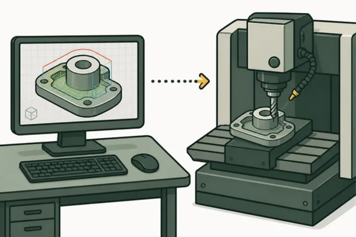
⌗Differences between CAD, CAM, and CAE
CAD (computer-aided design)
Computer-Aided Design
- The work, and the software, of creating, editing, and examining the 2D and 3D shape of a part on a computer and turning it into drawings and other documents. It replaces the drafting board and hand drawing.One source / reference[1]
CAM (computer-aided manufacturing)
Computer-Aided Manufacturing
CAE (computer-aided engineering)
Computer-Aided Engineering
- The work of using software to simulate a product's performance (strength, heat, flow, etc.) and check whether the design is good. It proceeds in three stages: pre-processing (entering shape, materials, and loads), solving (solver), and post-processing (viewing results).One source / reference[4]
Integrated CAD/CAM and standalone CAM
integrated CAD/CAM vs standalone CAM
- Integrated systems where CAM runs inside CAD (Fusion, SOLIDWORKS CAM, Creo's machining functions, Onshape CAM Studio, etc.) make it easy for toolpaths to follow when you change the shape. Standalone CAM and CAM embedded in another vendor's CAD (hyperMILL's SOLIDWORKS and Inventor integration, SolidCAM, etc.) are strong in accepting data from any CAD.[5][6][7][8][9][10][11][12]
→CAM workflow (from 3D model to machine)
- Prepare the 3D model
Related:Data formats,Drafting
- Define the stock and coordinate system (work origin)
- Choose tools and cutting conditions
Related:Tooling,Calculators
- Create the toolpath (tool path)
- Check with simulation
- Make the NC program with the post-processor
Related:G/M code dictionary
- Send it to the machine (memory operation, DNC)
- Check on the machine before cutting
- Set the tool length and work coordinate system on the machine, and check the motion using the NC control's graphic display and safe-operation functions before starting the actual cut. The most common causes of a first-run collision are mistakes in tool offset or work coordinate settings, and the wrong tool in the spindle.[16][28][15]
◇Types of CAM
2.5D milling
2.5-axis milling
3D (3-axis) milling
3-axis surface milling
Mill-turn (multitasking, Swiss-type)
mill-turn / Swiss-type
CAD/CAM pages
Toolpath types
Contour, pocket, hole, high-efficiency roughing, trochoidal; waterline, raster, surface-following, pencil, rest machining. Includes calculators for trochoidal slot milling and an initial depth-of-cut guide.
▤CAD/CAM software list
25 products, unranked. Filter by CAM or CAD category, strengths in machining, delivery form, and free or trial versions. Published prices are dated.
⇄Data formats
What STEP (AP203, AP214, AP242), IGES, Parasolid, ACIS, DXF, DWG, STL, and 3MF carry. Problems that occur in exchange.
⌖Coordinate systems, post, DNC
Work coordinate system G54, stock and tool library, the 4 stages of simulation, post-processor, DNC operation, and a checklist of common mistakes.
⟲5-axis machining
The difference between 3+2 and simultaneous 5-axis, machine configurations, NC functions such as tool center point control, calibration, common mistakes, and 5-axis calculations.
ACAD/CAM terms (35 terms)
| Term | English | Category | Meaning |
|---|---|---|---|
| CADkyado | Computer-Aided Design | Basics | Creating the 2D or 3D shape of a part on a computer, editing it, and putting it into drawings and other documents.[1] |
| CAMkyamu | Computer-Aided Manufacturing | Basics | Creating the commands that run a CNC machine tool (G-code, etc.) with software. In the broad sense, it also includes machining planning, simulation, and post-processing.[2][3] |
| CAEshi-e-i | Computer-Aided Engineering | Basics | Using software to simulate a product's performance in order to check a design or solve problems.[4] |
| Toolpath (tool path)tsūrupasu | toolpath / tool path | Basics | The route followed by the tool's cutting edge (or center). CAM calculates it from the model, the tool, and the conditions.[3][21] |
| CL datashi-eru dēta | cutter location data / CL data | Basics | Machine-independent tool position data output by CAM. A post-processor converts it into an NC program for each machine.[25] |
| Post-processor (post)posuto purosessa | post processor / post | Basics | Software that translates CAM path data into an NC program in the format of a specific machine and NC control.[25][3][26]→ G/M code dictionary |
| NC program (G-code)enu-shi purogramu | NC program / G-code | Basics | Machining commands that the NC control reads. CAM outputs them through the post.[2][3]→ G/M code dictionary |
| Setup (job)settoappu | setup / job | Basics | The group of operations done in one setup. It holds information on the stock, coordinate system, and the machine and tools used, and the machining operations are lined up inside it.[3][21] |
| Work coordinate system (WCS)waku zahyokei | work coordinate system / WCS / workpiece coordinate system | Coordinates and setup | A coordinate system placed to fit the part. The CAM WCS is the coordinate reference for the post-processed NC program, and on the machine you match it by registering it as G54 or similar.[14][15][16]→ G54–G59 |
| Machine coordinate systemkikai zahyokei | machine coordinate system | Coordinates and setup | A coordinate system specific to the machine. The origin of the work coordinate system is registered as a position within the machine coordinate system.[15]→ G53 |
| Stocksozai | stock | Coordinates and setup | The shape and size of the material before cutting. Entering it in CAM reduces air cutting and is also used to track the remaining stock.[3][30] |
| Tool librarykōgu raiburari | tool library | Coordinates and setup | A register of tool and holder shapes, dimensions, and so on.[3][7][9]→ Tooling |
| 2.5D machiningni-ten-go jigen kakō | 2.5-axis machining / 2.5D | Machining type | Machining of a flat shape by stepping Z down to a set depth.[3][29] |
| Indexed 5-axis (3+2 axis)warinashi go-jiku | 3+2 axis / positional 5-axis | Machining type | Tilts the tool orientation with the rotary axes and locks it, then does 3-axis machining in that attitude.[22][12][20] |
| Simultaneous 5-axis machiningdoji gojiku kako | simultaneous 5-axis machining | Machining type | Cutting while moving 3 linear axes and 2 rotary axes simultaneously.[20][9] |
| Multitasking (mill-turn)fukugō kakō | mill-turn / multitasking | Machining type | Turning and milling done in one machine. Synchronization of multiple spindles and turrets is required.[5][32][9] |
| Waterline machiningtōkōsen kakō | contour / Z-level / waterline | Toolpaths | A path that traces the contour of the shape at each constant height. Suited to steep slopes.[18][20][3] |
| Raster machiningsōsasen kakō | parallel / raster | Toolpaths | A path that reciprocates along parallel lines in XY while Z follows the surface. Suited to gentle surfaces.[18][20] |
| Surface-following machining (scallop)men-zoi kakō | scallop / constant stepover | Toolpaths | A path offset inward so that the spacing between passes stays constant on a curved surface.[18][20] |
| Pencil machiningpenshiru kakō | pencil | Toolpaths | A path that follows small corner radii and valleys to cut areas the previous tool could not reach.[18][20] |
| Rest machining (leftover machining)nokoshi-kezuri | rest machining | Toolpaths | A path that uses a smaller tool to cut only the areas the previous operation's tool left uncut.[19][20] |
| High-efficiency roughing (adaptive)kōkōritsu arakakō | adaptive clearing / high-efficiency milling | Toolpaths | A roughing method that varies the pass spacing so that the tool engagement stays below a set limit. Uses the side of the tool at deep depth of cut.[17][30] |
| Trochoidal millingtorokoido kakō | trochoidal milling | Toolpaths | A method that advances while drawing small circles and removes material bit by bit. Cuts slots and pockets with low cutting force.[35] |
| Swarf machiningsuwāfu kakō | swarf milling | Toolpaths | Machining with simultaneous 5-axis in which the side of the tool is placed against an inclined wall.[20][9] |
| Stepover (pitch)sutteppu ōbā | stepover / pick feed | Conditions | The spacing between adjacent passes. It affects the height of the cusps (ridges) on the finished surface.[18][35][36] |
| Axial depth of cut ap, radial depth of cut aejiku-hōkō kirikomi | axial depth of cut (ap) / radial depth of cut (ae) | Conditions | ap is the amount the tool engages in the axial direction, and ae in the radial direction. High-efficiency roughing and trochoidal milling use a small ae and a large ap.[35][17] |
| Machine simulationkikai shimyurēshon | machine simulation | Verification | Showing even the machine structure on screen to check collisions between tool, fixture, and machine, and stroke overruns.[9][32][31] |
| Collision checkkanshō chekku | collision check / interference check | Verification | Checking before machining whether the tool and holder will hit the part, fixture, or machine.[24][12][23] |
| NC verification softwareenu-shi kenshō sofuto | NC verification software | Verification | Software that reads the post-processed NC program itself and reproduces the machine's motion (VERICUT, NCVIEW, etc.).[23][24] |
| DNC operationdi-enu-shi unten | DNC / drip feed / remote buffer operation | Transfer | Operation that machines while sending NC data from an external device. Used for large programs that do not fit in the NC control's memory.[27] |
| Neutral format (intermediate file)chūritsu keishiki | neutral format | Data | A common format for exchanging shapes between different CAD and CAM systems. STEP and IGES.[37][38][39] |
| B-rep (boundary representation)bi-reppu | boundary representation / B-rep | Data | A way of representing a solid by the connections of the faces, edges, and vertices that enclose it. Used by the kernels of many CAD systems.[40][41] |
| Modeling kernelmoderingu kāneru | geometric modeling kernel | Data | The core software component that handles the shape calculations of CAD. Parasolid (Siemens) and ACIS (Spatial) are typical examples.[40][41] |
| PMI (product and manufacturing information)pi-emu-ai | product and manufacturing information / PMI | Data | Information such as dimensions, tolerances, and datums attached to a 3D model. There is semantic PMI, whose meaning software can read, and graphic PMI, which is appearance only.[42][43]→ Drafting |
| STL (triangle mesh)esu-ti-eru | STL / triangle mesh | Data | A format that represents a surface as a collection of triangles. It has no standard for units or color.[44] |
📚Sources
The CAD/CAM pages are based on software vendors' official pages and help, public pages of standards bodies and public institutions (Library of Congress, NIST, ISO), and university materials. Feature names and available operations differ by software and version, so check the help of the software you use.
- Siemens Digital Industries Software, “Computer-aided design (CAD) (glossary)”
- Siemens Digital Industries Software, “Computer-aided manufacturing (CAM) (glossary)”
- FreeCAD project, “CAM Workbench (FreeCAD Documentation)”
- Siemens Digital Industries Software, “Computer-aided engineering (CAE) (glossary)”
- Autodesk, “Autodesk Fusion product page (Japanese; includes pricing and personal-use description)”
- Dassault Systèmes (SOLIDWORKS), “SOLIDWORKS CAM”
- PTC「PTC Store: Creo Machining Suite」
- PTC (Onshape), “Onshape CAM Studio”
- Dassault Systèmes, “DELMIA Machining - Online Store (plans and prices)”
- OPEN MIND Technologies AG, “CAM software (hyperMILL introduction)”
- SolidCAM, “SolidCAM USA home page”
- Hexagon「WORKNC」
- Autodesk「Inventor LT 2020 Help: About Imported STEP and IGES data (Construction Environment)」
- Autodesk, “Fusion Help: Setup tab (milling and cutting) reference (how to define the WCS)”
- Mitsubishi Electric, “The Basics of CNC Machining Programming (for Machining center) e-Learning material (PDF)”
- Haas Automation, Inc., “Mill Operator's Manual 8 - Part Setup (online version)”
- Autodesk, “Fusion Help: 3D Adaptive Roughing (formerly Adaptive Clearing) reference”
- Autodesk「Fusion Help: Scallop Finishing reference」
- Autodesk, “Fusion Help: search results for rest machining (explanation of Rest Machining)”
- C&G Systems Inc., “CAM-TOOL”
- Autodesk「Inventor CAM 2020 Help: To Simulate and Post Process the Toolpaths」
- Autodesk, “Fusion for Personal Use Changes (Fusion Blog, 2020 announcement of changes and FAQ)”
- CGTech (VERICUT), “About VERICUT”
- Simpletech Co., Ltd., “Simpletech home page (NCVIEW)”
- Czech Technical University in Prague (Acta Polytechnica), “Vavruška P. Creating a Multi-axis Machining Postprocessor (Acta Polytechnica 52(4), 2012)”
- Autodesk「Autodesk Fusion Post Processor Library」
- Kumamoto University, Faculty of Engineering Technical Division, “DNC operation of an NC milling machine using a remote buffer (Dai Kurata, Technical Division Report FY2018)”
- Haas Automation, Inc., “Mill Operator's Manual 11 - Operation (online version)”
- Siemens Digital Industries Software「NX X Manufacturing Standard」
- Hexagon (ESPRIT), “ESPRIT Milling”
- Autodesk, “Autodesk Fusion with PowerMill (Japanese; pricing and purchase)”
- GibbsCAM (Sandvik group), “GibbsCAM home page”
- Hexagon (ESPRIT), “ESPRIT Wire EDM”
- CNC Software, LLC (Mastercam), “Sandvik to acquire leading CAM software company CNC Software Inc. (2021-08-25)”
- Sandvik Coromant, “Slicing and trochoidal milling (technical information)”
- Sandvik Coromant, “Profile milling (technical information)”
- Library of Congress, “STEP-file, ISO 10303-21 (Sustainability of Digital Formats, fdd000448)”
- National Institute of Standards and Technology (NIST), “Initial Graphics Exchange Specifications (in NIST SP 958)”
- University of Victoria (MECH 410 lecture materials), “CAD Data Exchange (10b)”
- Siemens Digital Industries Software「Parasolid」
- Spatial Corp. (Dassault Systèmes), “3D ACIS Modeler”
- National Institute of Standards and Technology (NIST), “STEP File Analyzer and Viewer”
- ISO, “ISO 10303-242:2014 Managed model-based 3D engineering (overview; a newer edition, ISO 10303-242:2025, exists)”
- Library of Congress, “STL (STereoLithography) File Format Family (fdd000504)”