Grinding Machine Tooling
How wheel dimensions are written and the shape numbers, how to read the marking of conventional wheels (e.g. WA60K8V) and superabrasive wheels, flange rules, maximum operating speed, and safety rules such as trial running (Japan's grinding machine construction standard and Industrial Safety and Health Regulations).
Printed from Kezuriba (kezuriba.net/en/tooling/grinder/)
▸How dimensions are written
- Conventional wheels
- In the order outside diameter (D) × thickness (T) × bore (H) mm. E.g. 305×25×76.2, 205×19×25.4[1][2][3]Types other than No. 1 and No. 2 need detailed dimensions or a drawing (Noritake)
- Superabrasive wheels
- Outside diameter × thickness × bore, plus the abrasive layer thickness (e.g. 200×15×50.8×3)[3][4]
- Standard
- —Not confirmed in public sourcesThe text and abstracts of JIS R 6211 and ISO 525 could not be retrieved from JSA and ISO, so they were not confirmed. Values are from manufacturer documents
▸Shape numbers
- Straight wheel[1][2][3]
- Cylinder (ring) wheel[1][3]
- Single-bevel wheel[1][3]
- Double-bevel wheel[1]1 source · reference
- Recessed one side wheel[1]1 source · reference
- Straight cup wheel[1]1 source · reference
- Recessed two sides wheel[1]1 source · reference
- Double cup wheel[1]1 source · reference
- Flaring cup wheel[1]1 source · reference
- Dish wheel[1]1 source · reference
- Saucer wheel (for saw sharpening)[1]1 source · reference
- Relieved and recessed types[1]1 source · reference
- Offset (depressed-center) type[1][2]New Resiston's example is No. 27
- Double dovetail type (formerly No. 10)[1]1 source · reference
▸Superabrasive wheel shapes
Diamond and CBN wheels use shape type designations such as 1A1 to describe the shape of the core and the abrasive layer[3]1 source · reference
▸Edge profiles
▸Conventional wheel marking
- Order
- Abrasive, grit size, grade, structure, bond, sub-symbol (manufacturer's own), maximum operating speed[1][2][3]
- Examples (by manufacturer)
- How to read the example
- WA60K8V = white alumina abrasive, grit 60, grade K, structure 8, vitrified bond[1][3]
- Abrasive
- Grit size
- Grade (hardness)
- Letters A (soft) to Z (hard)[1][2][3]
- Structure
- Rule Expresses the abrasive volume as a number; the smaller the number, the denser (more abrasive grain), the larger, the more open[1][2][3]
- Range (by manufacturer)
- 1 (dense) to 14 (open)[3]
- Bond
- Sub-symbol
- The variation symbol after the bond is manufacturer-specific[2][3]
▸Superabrasive wheel marking
- Order
- Abrasive, grit size, grade, concentration, bond[3][4]
- Examples (by manufacturer)
- Abrasive (by manufacturer)
- Grade (by manufacturer)
- A (soft) to R (hard)[3]
- Concentration
- Concentration 100 = 25 vol% abrasive (concentration ÷ 4 = abrasive volume %)[5]1 source · reference
- Concentration (by manufacturer)
- Marking examples from 125 (low) to 200 (high)[3]
- Bond (by manufacturer)
- JIS notes
- In JIS the symbol for resin bond is B, but manufacturers often mark their own bond names (e.g. BDH)[4]1 source · reference
- Definition
- JIS B 4131 calls a tool with an abrasive layer mainly on the periphery or face of a metal core a "wheel", to distinguish it from the grinding wheels of JIS R 6210 and R 6212[6]1 source · reference
- Definition of concentration 100
- —Not confirmed in public sources"4.4 ct/cm³ = concentration 100" appeared in a search-result snippet but could not be confirmed in the body text of the manufacturer documents retrieved
▸Flanges
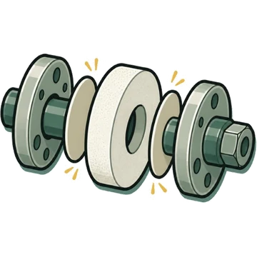
- General
- When mounting a grinding wheel on a grinding machine, use flanges that conform to the structural standard (ring-type and disc-type backing plates, wheels with nuts, segments, mounted wheels, flat wheels for precision internal grinding, etc. may use other mounting fixtures)[7]1 source · reference
- Material
- Made of material with tensile strength equal to or greater than gray cast iron (Class 2 of JIS G 5501-1956), and must not deform[7]1 source · reference
- Same dimensions on both sides
- Fixed-side and movable-side flanges must have equal diameter and contact width[7][8][1]
- Fixed side
- The fixed-side flange is secured to the wheel spindle by key, screw, shrink fit, press fit, etc., and the tightening screw must tighten in the direction of rotation[7]1 source · reference
- Straight flange
- Diameter At least 1/3 of the grinding wheel diameter[7][9]
- Relief Relief of 1.5 mm or more[7][9]
- Contact width
- D≦65 More than 0.1Df and less than 0.26Df
- 65<D≦355 More than 0.08Df and less than 0.18Df
- D>355 More than 0.06Df and less than 0.18Df
- Reinforced cut-off wheel For reinforced cut-off wheels with a maximum operating speed of 80 m/s or less (reinforced for a cutting load of 700 N or more), 1/4 or more is acceptable[7][9]Kuretoishi gives the same content in old units (4,800 m per minute, 71 kg)
- Sleeve / adapter flange
- Type Df ≥ κ(D − H) + H (H = pilot diameter of the flange)[7][9]
- Approach angle
- D<610
- Normal 0.13
- High-speed 0.15
- 610≦D<760
- Normal 0.11
- High-speed 0.13
- 760≦D<1065
- Normal 0.1
- High-speed 0.12
- D≧1065
- Normal 0.08
- High-speed 0.1
- D<610
- Adapter limit Adapter flanges must not be used for wheels other than normal speed (high speed)[7][9]
- Safety flange
- Straight wheel At least 2/3 of the wheel diameter
- Double taper At least 1/2
- Relief At least 1.5 mm
- Contact width At least 1/6 of the flange diameter
- Taper contact For double-bevel wheels, a slope of at least 1/16 on the contact surface
- Blotter
- Use wheel blotters (paper packing) larger than the flange diameter. For safety flanges for straight wheels, use rubber blotters[7][1][8]
▸Maximum operating speed
- Definition
- The upper limit of peripheral speed (m/s) at which the wheel can be used safely. It must not be exceeded[10][1][9][2]
- Normal operating speed limit (m/s)
- Item
- Grinding wheel Straight wheel (unreinforced, general purpose)
- Inorganic 33
- Organic 50
- Grinding wheel Straight wheel (unreinforced, for heavy-duty grinding)
- Inorganic —
- Organic 63
- Grinding wheel Straight wheel (for thread and groove grinding)
- Inorganic 63
- Organic 63
- Grinding wheel Straight wheel (for crankshaft and camshaft grinding)
- Inorganic 45
- Organic 50
- Grinding wheel Straight wheel (reinforced, D≤100 and T≤25)
- Inorganic —
- Organic 80
- Grinding wheel Straight wheel (reinforced, 100<D≤205 and T≤13)
- Inorganic —
- Organic 72
- Grinding wheel Single-bevel, double-bevel, recessed one side, recessed two sides, safety, dish, saucer (saw sharpening)
- Inorganic 33
- Organic 50
- Grinding wheel Cylinder (ring) wheel
- Inorganic 30
- Organic 35
- Grinding wheel Straight cup, flaring cup
- Inorganic 30
- Organic 40
- Grinding wheel Disc type (Jisuku)
- Inorganic 33
- Organic 45
- Grinding wheel Offset (depressed-center) type (D≤230, T≤10; unreinforced / reinforced)
- Inorganic —
- Organic 57/72
- Grinding wheel Cut-off wheels (unreinforced / reinforced)
- Inorganic —
- Organic 63/80
- Item
- Conversion for imported wheels
- 8500 45
- 9500 50
- 12000 60
- 16000 80
- 20000 100
- 6500 ft/min 33
- Size limits by operating speed
- Other than normal speed, up to 45 m/s (straight wheels, etc.) D≤1065, bore H≤0.6D
- 45〜60 m/s D≦1065、H≦0.5D
- 60–80 m/s (straight, offset, cut-off wheels, etc.) D≤760 (1500 for cut-off), H≤0.33D
- 80〜100 m/s D≤760 (1500 for cut-off), H≤0.2D
- Normal speed H≦0.7D
- Spin test
- Wheels of 100 mm diameter or more are spin-tested at 1.5 times the maximum operating speed for each lot[7]1 source · reference
- Color bands (by manufacturer)
- Color bands on high-speed wheels: up to 45 m/s = blue, 45–60 = yellow, over 60 = red (about 20 mm wide)[9]
- Marking requirements
- Wheels must be marked with the manufacturer's name, bond type and maximum operating speed (for diameters under 75 mm, marking per smallest packaging unit is acceptable)[7]1 source · reference
▸Rules for use
- Trial run
- Trial run of at least 1 minute before starting work, and at least 3 minutes after changing a wheel[10][8]
- Use of the side face
- Do not use the side of a wheel unless it is intended for side use[10][9]
- Wheel guard
- Provide a guard when a rotating wheel may be hazardous (except diameters under 50 mm)[10]1 source · reference
- Work rest
- On bench and pedestal grinders, the gap between the work rest and the wheel periphery must be adjustable to 3 mm or less, and the gap between the guard and the periphery to 10 mm or less[7]1 source · reference
- Usage limits (by manufacturer)
- Guide to the wear limit: for straight wheels, down to 1/10 of the portion protruding from the flange; for recessed wheels, down to 1/5 of the portion excluding the recess[9]
- Bore tolerance (by manufacturer)
- Bore tolerance for machine grinding: 1.6≤H≤50: +0.16/0, 50<H≤80: +0.19/0, 80<H≤180: +0.25/0 … (when the shaft side is f7 or better)[9]
▸Machine-side mounting
- Wheel bore diameter by machine
- Wheel spindle taper
- —Not confirmed in public sourcesNo public source was found that gives wheel spindle end tapers or flange mounting dimensions for surface and cylindrical grinders (probably handled in each model's instruction manual)
📚Sources
Values with no mark agree across two or more independent publishers. Values that differ between manufacturers are shown side by side rather than reduced to one.
- Noritake Co., Limited, "General-purpose Resipro / Bitopro general catalog vol1.2" (technical data: grinding wheel marking, overview, maximum operating speed)
- New Resiston Corporation, "Basic Knowledge of Grinding Wheels VI: How Wheels Are Marked"
- Kure Grinding Wheel Co., Ltd., "Basic Knowledge of Grinding Wheels: Specification Marking"
- Tokyo Diamond Tools Mfg. Co., Ltd., "What Is a Diamond Wheel?" (examples of wheel specification marking)
- Noritake Co., Limited, "NORITAKE TECHNICAL JOURNAL technical lecture 'Understanding Wheel Structure (Structure and Concentration)'"
- A.L.M.T. Corp., "Basics of Diamond and CBN Tools <Grinding Wheels>"
- Ministry of Health, Labour and Welfare (MHLW), "Grinding Machine Construction Standard (Ministry of Labour Notification No. 8 of 1971, 3 pages)"
- Kure Grinding Wheel Co., Ltd., "Using Grinding Wheels and Precautions"
- Kure Grinding Wheel Co., Ltd., "Safe Handling and Accident Prevention"
- e-Gov Law Search (Digital Agency), "Ordinance on Industrial Safety and Health, Articles 117–120 (grinding wheels)"
- Nagase Integrex Co., Ltd., "Precision Surface Grinding Machine SGW/M SERIES specifications"