The 3-2-1 principle, datum surfaces, locating pins and diamond pins, clamping principles, bushings, and poka-yoke. 16 terms. For each term: meaning, how to show it on a drawing, an example, common mistakes, and JIS vs. ASME differences.
Printed from Kezuriba (kezuriba.net/en/drafting/jig/)
Degrees of freedomjiyudodegrees of freedom
The number of directions in which a body can move independently. In locating, you stop every direction the workpiece could move (constrain it) so its position is fixed uniquely. Pressing it against three mutually perpendicular datum surfaces constrains it completely.[1][2]
Degrees of freedom: a body in space can translate in 3 directions and rotate about 3 axes. A jig stops all 6 with locators and clamps so the position is fixed uniquely.
How to write it on the drawing
Counting 12 movementsSome teaching materials count the + and − direction of each axis separately, giving 12 movements. They explain that the 6 points of the 3-2-1 principle stop 9 of them and the clamps stop the remaining 3.[1]
3-2-1 principlesan-ni-ichi no gensoku3-2-1 principle / 3-2-1 rule
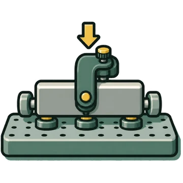
A locating principle that fixes the position of a rectangular workpiece uniquely by supporting it at 6 points in total: 3 on the bottom face, 2 on a side face, and 1 on an end face.[3][4][1]
3-2-1 principle: 3 points on the bottom, 2 on the long side, and 1 on the end (6 points in total) fix the position of a rectangular block
How to write it on the drawing
3 points on the bottom faceThree pins (rests) support the bottom face and stop vertical movement and rotation about two axes.[3][1]
2 points on the long side faceTwo pins stop movement in one direction and rotation about the vertical axis.[3][1]
1 point on the remaining faceOne pin stops movement in the last remaining direction.[3][1]
Clamp against the restsIn the direction opposite the pins, clamps press the workpiece against the rests.[1]
Spread the points apartPlace the rest points as far apart as possible.[1][5]
Example100×60×20 plate: put three rests at the corners of a large triangle on the bottom face, two pins on the long side, and one pin on the short side, then clamp the plate against the bottom and side pins.(An example built from the rules in the sources)[3][1]
Common mistakes
Supporting a flat face with 4 or more fixed pinsWhy: because of variation in the workpiece face, one point lifts off and the workpiece sits differently each time.Fix: support the datum surface at 3 points; if more support is needed, use spring-loaded or adjustable auxiliary supports.[1]
Supporting a workpiece that is moved by force with only the 3-2-1 pinsWhy: machining forces can move the workpiece.Fix: review the shape and number of the pins and arrange them to resist the direction of the force.[3][4]
The faces or pins on the jig that the workpiece is pressed against to fix its position. Types: an integral type machined out of the jig body, an assembled type made of separate parts, and a pin type using standard pins.[3][5]1 source (for reference)
How to make locators: an integral type machined from the jig body, an assembled type with separate parts, or a pin type with standard pins. With the assembled and pin types only the locator needs replacing, and highly wear-resistant materials can be used.
How to write it on the drawing
Choose the workpiece face to use as the datumIf possible, use a machined face or hole, and take the important face that is the origin of the drawing dimensions as the datum.[1][6]
Make it replaceableAssembled and pin types, where only the locating part is replaced, can use highly wear-resistant materials.[3]
First operation on cast surfacesFor the first operation on a casting or forging, locate it temporarily on two sides or similar, machine the bottom face, and use that face as the datum from then on.[1]
Common mistakes
Building up the datum surface as an integral partWhy: it takes a lot of machining, and when it wears you have to repair the whole jig.Fix: make the locating parts or pins replaceable.[3]
A cylindrical pin inserted into a hole in the workpiece or part to fix its position. When two are used, one is left as a full round (cylindrical) pin and serves as the position datum, and the other is made a diamond pin.[7][1][4]
Locating pins: space the two pins widely and give them different heights so that the taller one enters first. Give the tips a taper or radius to guide them into the holes. The second pin is a diamond pin that prevents rotation.
How to write it on the drawing
Wide spacing between the two pinsTake a long spacing between the pins and choose symmetric positions.[5][1]
Tip shapeChoose a ball nose, cone, or chamfer for easy insertion and to protect the workpiece. For light workpieces loaded by hand, a larger tip taper angle of up to 60° is typical; for large workpieces or automated machines, 10–30° is common.[7][8]
Give them different heightsThe taller pin gives a rough alignment first, and the shorter pin locates accurately.[7]
FitIn MISUMI's example, for an H7 hole the locating side is h6 and the side fixed to the base is g6.[9]
Common mistakes
Making pins that cannot be replacedWhy: both pins and holes wear and accuracy drops.Fix: make them replaceable, for example by providing a hole to push the pin out.[7]
The cylindrical pin with part of the cylinder cut away, used as the second pin when locating with two holes. It has relief along the line connecting the two hole centers, so it absorbs variation in hole spacing, and it constrains only the perpendicular direction to stop rotation.[7][1][4]
The diamond pin is relieved on both sides along the line joining the two holes and stops only the perpendicular direction (rotation)
How to write it on the drawing
Direction to cutCut away the area near the line connecting the two hole centers so that the remaining arcs contact the hole in the direction perpendicular to that line.[7]
Combine with a round pinThe first (round) pin fixes the position and the second (diamond) pin fixes the orientation (rotation).[7][1]
ExampleTwo holes spaced 100±0.05 apart: insert a round pin in one and, in the other, a diamond pin cut along the line connecting the two holes. The diamond pin's relief absorbs the spacing variation and only rotation is stopped.(An example built from the rules in the sources)[7][1]
Common mistakes
Using two round pinsWhy: because of variation in hole spacing, the workpiece will not go on, or is forced on and galls (over-constraint).Fix: make the second pin a diamond pin.[1][8][5]
Orienting the cut 90° wrongWhy: it cannot absorb the variation in hole spacing and does not stop rotation.Fix: mount it so the cut flats point along the line connecting the two holes.[7]
Stopping the same direction of motion with two or more elements at the same time. Part variation can then keep parts from fitting, or put excessive force on them.[8][5][1]
Over-constraint: two round pins stop the same direction (the line joining the two holes) twice, so even a small error in hole spacing keeps the workpiece from going on. Make the second pin a diamond pin to relieve that direction (offset exaggerated).
How to write it on the drawing
Constrain in 3 directionsLocate by constraining in 3 directions. Enclosing the part from 4 directions makes it impossible to insert or remove.[5]
Avoid fitting in two places at onceAn assembly that must engage in two places at the same time is not feasible, so give the pins different heights so they engage one after the other.[8][7]
Clamping principleskuranpu no gensokuclamping principles
A clamp presses the located workpiece against the rests and datum surfaces and holds it so that it does not move under cutting force or vibration. It must not damage or deform the workpiece.[1][10][11]
Illustration
How to write it on the drawing
Push toward the restsApply the clamping force toward the supporting and locating surfaces, at a rigid part of the workpiece.[1]
Take cutting force with the restsPlace the datums where they can resist the direction of cutting thrust and torque.[11][1]
Do not deform the workpieceChoose a position and direction where the clamping force does not exceed the workpiece's deformation strength, and if necessary clamp over an auxiliary support.[10]
Fast and secureFor frequently used jigs, make operation simple and quick and use a construction that does not loosen from vibration.[1]
Do not obstruct loading and unloadingMake sure opening and closing the clamp does not get in the way of loading and unloading the workpiece.[1]
Common mistakes
Clamping a rigid body such as ceramic directly with a screwWhy: it hardly deforms elastically, so it cracks if tightened hard.Fix: hold it with spring force or air pressure.[12]
Clamping at a position with no support underneathWhy: the workpiece deflects and springs back when released, so accuracy is lost.Fix: clamp directly over a rest or over an auxiliary support.[10][1]
Cutting force direction and locatingsessaku-ryoku no mukilocating against cutting forces
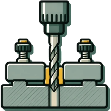
Identify the direction and magnitude of the forces on the workpiece during machining (such as drill torque and thrust), and place the locating datums so that they can resist them.[11][1]
Cutting force direction and locating: drill thrust (downward) is taken by the bottom rests, and torque (clockwise seen from above) is taken by a pin placed on the side it tries to rotate toward. The clamp must not take the cutting force.
How to write it on the drawing
Identify the forcesList all the forces on the workpiece and find their directions and magnitudes.[11]
Make the datum structure able to resistPut datum surfaces and pins in the direction of the force, and do not make the clamp take the cutting force.[11][1]
ExampleDrill jig: arrange the bottom rests to take the downward thrust and the side pins to take the rotational torque. If the pin is badly placed, the torque turns the workpiece.[11]
Common mistakes
Placing pins without considering the direction of cutting forceWhy: locating becomes unstable, leading to broken workpieces or tools, and accidents.Fix: decide the datum layout from the direction and magnitude of the forces.[11]
Auxiliary support (work support)hojo shijiwork support / auxiliary support
Additional support from below for large or thin workpieces that would deflect under cutting or clamping force with only the three rests. It supports without locating, so make it spring-loaded or adjustable.[1][10]
Auxiliary support: with only 3 rests, thin or large workpieces deflect under cutting and clamping force. In addition to the locating rests, add spring-loaded or adjustable supports underneath (deflection exaggerated).
How to write it on the drawing
Provide them separately from the locating restsSeparately from the locating rests, provide spring-loaded or adjustable supports under the places that deflect.[1][10]
Common mistakes
Making the auxiliary support a fixed pinWhy: it fights with the 3 datum points, so the workpiece lifts off or changes position.Fix: use a spring-loaded or adjustable support.[1]
A hardened sleeve pressed into a jig plate (bushing plate) to guide drills and reamers and give hole position accuracy.[1][13]
IllustrationJig bushing: a hardened sleeve that guides the drill to locate the hole. Leave just enough space to the workpiece for chips to escape. Too close and chips clog; too far and the drill wanders.
How to write it on the drawing
Make it replaceableUse a replaceable construction so accuracy is maintained as it wears.[13][1]
Air reliefWhen a long pin goes into a bushing, without an air-relief groove or relief hole it is hard to pull out.[13]
Standard: JIS B 5201 "Jig bushes and their accessories".[14]
Burr and chip countermeasuresbari, kirikuzu taisakuburr and chip relief
Burrs, chips, and foreign matter caught on the datum surface reduce locating accuracy, so the construction must be easy to clean and must not trap them.[15][16][17][18]1 source (for reference)
Burr and chip countermeasures: put the datums higher than the jig top surface and contact the workpiece with small rests instead of the whole face, so chips fall below and are not trapped. Add relief at workpiece corners (where burrs form).
How to write it on the drawing
Raise the datumsPlace the datums higher than the jig top surface so chips fall below.[15]
Use small datumsInstead of the whole face, support the workpiece on small wear-resistant pins.[15]
Relief at cornersProvide relief where the workpiece corners (where burrs form) would contact.[16]
For hole datums, shape the pinA pin with a radiused tip that is longer than the workpiece thickness can be inserted without touching the burr at the hole.[17]
Chamfer when supporting on a faceChamfer the datum face side to avoid the effect of foreign matter.[18]
Common mistakes
Inserting into a hole with a pin that has only a small C chamfer at the tipWhy: it touches the burr, drags it in, and traps it on the datum surface.Fix: choose the tip shape and length so the pin goes in without touching the burr.[17]
Poka-yoke (mistake-proofing against wrong setup)pokayokepoka-yoke / fool-proofing
Measures that keep the operator from setting the workpiece backward or in the wrong position, or from clamping it wrongly. One principle of jig design is to make clamping and locating methods foolproof.[1]1 source (for reference)
Poka-yoke: adding one pin to match the notch in an asymmetric workpiece means that if it is flipped or turned, it hits the pin and cannot be set.
ExampleAsymmetric workpiece: place the locating pins in asymmetric positions so the workpiece will not go on if flipped or turned.(An example built from the rules in the sources)[1]
Match the drawing datums to the fixture's locating referencesdatamu to jigu kijunaligning fixture locators with drawing datums
The idea of matching the faces and holes the jig locates the workpiece on to the datums on the drawing (and their priority order) and to the faces that are the origin of dimensions.[1][6][2]
Match the drawing datums to the jig datums: primary datum A to the 3-point rests, secondary B to the 2 pins, and tertiary C to the 1 pin, and clamp against each. You can machine on the same datums used for measuring.
How to write it on the drawing
Primary datum on the bottom restsMatch datums A, B, and C, in that order, to the faces supported at 3, 2, and 1 points.[2][3]
Use the assembly reference positionMake the reference position set by the assembly specification the jig datum as well.[6]
Common mistakes
Machining and measuring from a face different from the drawingWhy: if you measure from a different face than the drawing's datum, the error between those faces gets mixed into the result.Fix: make the drawing datums the jig datums.[1][6]
Replaceability of wear partsmamo-buhin no kokanseireplaceable wear parts
Locating pins, bushings, and datum parts wear with use and lose accuracy, so harden them (by quenching, for example) and make them replaceable.[7][13][1][3]
Replaceability of wear parts: give locating pins a hole to push them out from below; for bushings, put a slip bushing into a fixed liner pressed into the jig and hold it with a lock screw. When worn, replace only the slip bushing.
How to write it on the drawing
Replaceable mountingProvide a hole so pins can be pulled out, and make bushings replaceable.[7][13]
V-block (locating with a V-groove)bui burokkuV-block / vee block
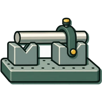
A method of locating a cylindrical workpiece by seating it in a V-groove, which centers it naturally. Used for locating a cylinder along its length and for centering.[5][1]
Illustration
How to write it on the drawing
Support round parts in a VRound bars and pipes are self-centered with V-blocks or cones.[1]
1 hole + V-blockOne hole combined with a V-block can also stop rotation.[1]
Also used for measurementClamping a ball between two V-blocks makes its center a datum point.[19]
Requirements for jigs and fixtures (workholders)jigu ni motomerareru jokenworkholder requirements
Requirements for a jig: hold the workpiece stably and securely to the required accuracy; easy to load and unload; easy to do related work; durable and rigid; interchangeable and uniform when there are several.[6][1]
How to write it on the drawing
Choosing the datum surfaceChoose the datum surface for locating the workpiece.[6]
Avoid disturbancesUse a construction that avoids the effects of foreign matter and dirt.[6]
Material selectionChoose materials that avoid scratching the workpiece and wear of the jig.[6]
Explanations without a mark are those on which two or more sources from different publishers agree. Because the text of the standards is paid, they were checked against technical materials from measuring-instrument and parts manufacturers, teaching materials from universities and public testing institutes, and public pages of the standards, and the explanations are written in Kezuriba's own words. The diagrams of the entry fields were drawn by Kezuriba.