5-AXIS MACHINING5-axis machining
5-axis machining adds two rotary axes to the three linear axes (X, Y, Z) so you can cut while also changing the tool orientation. We start with the difference between “3+2 (indexed)” and “simultaneous 5-axis,” then cover machine types, NC functions, calibration, and where things tend to go wrong, all checked against public manufacturer and standards documents.
Most parts are fine
with 3+2!
First, the difference.
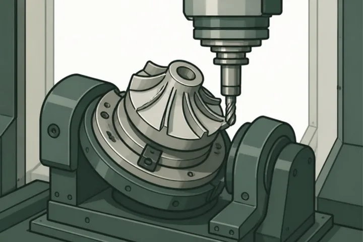
◇3+2 machining vs. simultaneous 5-axis machining
5-axis machining
3+2 machining (indexed machining, tilted-plane machining, multi-face machining)
Simultaneous 5-axis machining
5-face machine (not the same as a 5-axis machine)
- A gantry machining center that automatically changes attachment heads (extension heads, 90° angular heads) to machine the top and four sides of a workpiece. The tool orientation only switches between fixed angles; it is not tilted continuously by rotary axes.One source / reference[10]
≡Quick comparison
| 3+2 machining | Simultaneous 5-axis machining | |
|---|---|---|
| Tool orientation | Static (indexed and locked) | Dynamic (changes while cutting)[1][4][2][6][7] |
| How the program is made | You can write an ordinary 3-axis program (fixed cycles can be used) on the tilted plane. It can also be written by hand. | CAD/CAM required[4][6][7][11] |
| Main NC functions | Tilted working plane commands (FANUC Tilted Working Plane / Mitsubishi Electric tilted plane machining command), Siemens CYCLE800, Heidenhain PLANE, Haas G254 (DWO) and G268 | Tool center point control (FANUC/Mitsubishi Electric G43.4 etc.), Siemens TRAORI, Heidenhain M128 / FUNCTION TCPM, Haas G234 (TCPC)[1][5][6][12][13][9][8][11][14] |
| Suited parts (3+2) | Most general parts can be done with 3+2 (up to simultaneous 4-axis). Holes and pockets on tilted faces, multi-face machining, roughing and semi-finishing of 3D shapes, making tools and fixtures | —[2][7] |
| Suited parts (simultaneous 5-axis) | — | Overhanging shapes such as impellers and blisks, turbine and aero-engine parts, aircraft structural parts, free-form surfaces of dies and molds, finishing of deep recesses and shapes with many curvature changes[1][2][7] |
| Difficulties of simultaneous 5-axis | — | The motion is complex, so creating and verifying NC programs takes time; it is hard to read the motion at the machine; and with many moving axes, rigidity is hard to maintain[15] |
✓What do you gain from 5 axes?
- You can reduce setup changes (re-fixturing the workpiece). Waiting between operations and machining time go down, and accuracy improves because the fixturing error introduced by each re-fixturing disappears.[6][7][16][17]A FANUC development report (s6) splits the benefit into two: ‘less waiting between operations and shorter machining time’ and ‘eliminating fixturing error from setup changes.’ Manufacturer product pages (Mazak, Okuma) describe it as ‘process consolidation.’
- Tilting a ball end mill lets you avoid cutting with the near-zero surface speed center, which gives a better finish (cutting with the center crushes the material instead of cutting it).[18][15]In an experiment by the Kanagawa Institute of Industrial Science and Technology (KISTEC), the tilted surface had more gloss, but the surface roughness Rz was smaller without tilt (lead and tilt angles of 0°). The conclusion: the way you tilt must be chosen according to whether you prioritize appearance (surface quality) or surface roughness (s42).
- Because the angle between the tool and the surface can be kept constant, the surface roughness stays uniform.One source / reference[6]
5-axis machining pages
5-axis machine configurations
The three types (head-head, table-table, head-table) with their advantages and drawbacks, the names and directions of rotary axes A, B, C, vertical vs. horizontal machines, and multitasking machines.
G5-axis NC functions
Tool center point control, tilted working plane commands, and 3D tool radius compensation. A comparison of commands by NC maker, G93 inverse time feed, tool length and the center of rotation.
◎Calibration, collision, workholding and tools
Kinematics calibration with a reference sphere, accuracy test standards, collision checking and simulation, 5-axis vises, tool stick-out and how to tilt a ball end mill.
!Common 5-axis mistakes
Singularities, the two solutions of a rotary axis and the long way around, feed units, forgotten tool length, and forgetting to cancel a tilted plane. A checklist to verify on the shop floor.
÷5-axis calculations
F value for G93 inverse time feed, ball end mill tilt angle, angles from a direction vector, and the shortest way for a rotary axis to turn.
⌗CAD/CAM
CAM workflow, toolpath types, a list of software, data formats (STEP, IGES, Parasolid), coordinate systems and post-processors.
A5-axis machining terms
| Term | English | Meaning |
|---|---|---|
| 5-axis machinegojiku kakoki | 5-axis machining center | A machining center that adds two rotary axes to the three linear axes and can cut while also changing the tool orientation.[1][3] |
| 3+2 machiningsan purasu nijiku kako | 3+2-axis machining / tilted plane machining | Machining in which the rotary axes set the tool orientation and lock, and the three linear axes cut. Also called indexed machining or tilted-plane machining.[4][5][7] |
| Simultaneous 5-axis machiningdoji gojiku kako | simultaneous 5-axis machining / 5-axis simultaneous | Machining that interpolates the three linear axes and two rotary axes simultaneously, changing the tool orientation while cutting.[2][6][7] |
| Indexed machiningwaridashi kako | multi-face machining | Machining in which a rotary axis is indexed to a fixed angle and locked, and cutting is done in that orientation. Mitsubishi Electric uses the term to include multi-face and tilted-plane machining.[7][4] |
| 5-face machininggomen kako | 5-face machining / 5-sided machining | Machining the top and four sides in a single setup. It is done both on gantry machines that swap attachment heads (5-face machines) and with 3+2.[10][25] |
| Process consolidationkotei shuyaku | Combining operations that were spread across several machines and setups into one machine and fewer setups.[6][17][16] | |
| Tool center point controlkogu sentan-ten seigyo | tool center point control (TCP) / TCPM (Heidenhain) / TCPC (Haas) / TTPC (Mazak) | A function in which the NC automatically calculates the linear-axis compensation so that the tool tip follows the programmed position even when rotary axes turn.[1][6][13][9][14] |
| 5-axis transformationgojiku henkan | 5-axis transformation / TRAORI (Siemens) | An NC function that converts the tool tip position and orientation written in workpiece coordinates into the motion of each machine axis. Corresponds to Siemens' tool center point control.[1][2] |
| Tilted working plane commandkeishamen kako shirei | tilted working plane (TWP) / inclined surface machining command / PLANE (Heidenhain) / CYCLE800 (Siemens) / feature coordinate system G268 (Haas) | A function that defines a coordinate system along a tilted face so you can machine it as if it were the XY plane.[5][7][13][1][11] |
| Tilted coordinate systemkeisha zahyokei | tilted coordinate system / feature coordinate system | The coordinate system along the machining surface that is defined in tilted-plane machining.[7][11] |
| Tool axis direction controlkogu jiku hoko seigyo | tool axis direction control / tilted working plane indexing | A function that automatically indexes the rotary axes so the tool is perpendicular to the tilted plane, and links the tilted coordinate system to the rotary axes.[26][7] |
| Work coordinate systemwaku zahyokei | workpiece coordinate system (WCS) | A coordinate system referenced to the workpiece origin. Programs are usually written in it, and the NC converts it to the machine coordinate system (MCS).[1][11] |
| Machine coordinate systemkikai zahyokei | machine coordinate system (MCS) | A coordinate system referenced to the machine origin.[1][19] |
| Kinematicskinemateikusu | kinematics / machine kinematics | The geometry of how the machine axes are arranged and the positions and orientations of the rotary axes. The NC calculates the tool tip position using the registered kinematics.[1][27] |
| Head-head typeheddo heddo gata | head-head kinematics / head rotation type | A configuration with both rotary axes on the spindle head side.[2][6][3] |
| Table-table typeteburu teburu gata | table-table kinematics / table rotation type | A configuration with both rotary axes on the table side. The trunnion type is the typical example.[2][6][3] |
| Head-table type (mixed type)heddo teburu gata | head-table kinematics / mixed kinematics / mixed type | A configuration with one rotary axis on the spindle head side and one on the table side.[2][6][3] |
| Trunnion tabletorunion teburu | trunnion table | A table with a tilt axis plus a rotary axis, in which the rotary table is supported at both sides and tilted.[28][17][16] |
| Tilt-rotary table (swivel rotary table)chiruto rotari teburu | tilt-rotary table / swivel rotary table / tilting rotary table | A table that combines a tilting axis and a rotating axis into one. The name used by Mazak, DMG MORI, GROB, Hermle and others.[16][29][25][30] |
| Swivel headsuiberu heddo | swivel head | A spindle head that tilts (swivels) on a rotary axis.[31][1] |
| Tilt axiskeishajiku | swivel axis | A rotary axis that tilts the tool or the workpiece. The A axis or the B axis, depending on the machine.[32][22] |
| Center of rotation (pivot)kaiten chushin | center of rotation / pivot point / MRZP (Haas: machine rotary zero point) | The center about which a rotary axis turns. If the center of rotation held by the NC differs from the real machine, machining that moves the rotary axes will show errors.[9][33][26][34] |
| Pivot lengthpibotto cho | pivot length | (On machines whose spindle head tilts) the distance from the center of rotation of the tilt axis to the spindle end (the tool reference).[35] |
| Kinematics calibration (measuring the rotary axis center)kinemateikusu kosei | kinematics calibration / rotary axis position calibration / KinematicsOpt (Heidenhain) / CYCLE996 (Siemens) | Measuring the center and orientation of the rotary axes with a reference sphere and touch probe, and correcting the NC's machine configuration parameters.[1][26][27] |
| Reference sphere (calibration sphere)kijun kyu | datum sphere / calibration sphere | A sphere with an accurately known radius. It is fixed on the table and measured during kinematics calibration.[27][26][28][35] |
| Ballbarboru ba | ballbar | A telescoping measuring instrument with a ball at each end. It measures the change in distance between the tool tip and the workpiece during circular moves or simultaneous 5-axis motion.[14] |
| Singularitytokuiten | singular point / singularity | A tool orientation near which the rotary axes become unstable and swing around widely.[6] |
| Inverse time feedgyaku jikan okuri | inverse time feed (G93) | A way of commanding feed in which F means ‘the block is completed in 1/F minutes.’ Used in 4- and 5-axis CAM output.[36][21][37] |
| Direction vectorhoko bekutoru | direction vector / tool orientation vector / A3/B3/C3 (Siemens) / I/J/K (FANUC type II) | The tool orientation expressed as X, Y, Z components. It does not depend on the machine configuration, unlike writing rotary axis angles.[1][6] |
| Lead anglerido kaku | lead angle / LEAD (Siemens) | The angle the tool is tilted in the feed (travel) direction.[18][1] |
| Tilt anglechiruto kaku | tilt angle / TILT (Siemens) | The angle the tool is tilted in the direction perpendicular to the feed direction (Siemens defines TILT as a rotation about the surface normal).[18][1] |
| Surface normal vectormen no hosen bekutoru | surface normal vector | A vector perpendicular to the machining surface. Used as the reference for 3D tool radius compensation and LEAD/TILT. Output by CAM.[1][13] |
| 3D tool radius compensationsanjigen kogu-kei hosei | 3D cutter compensation / 3D tool radius compensation | A function that compensates the tool radius in three dimensions using the surface normal and the tool orientation.[1][5][13] |
| Tool orientation controlkogu shisei seigyo | tool posture control / vector interpolation of orientation | A function that interpolates between the tool orientations at the start and end points so that side milling produces a flat surface.[5][6][34] |
| Workpiece setup error compensationwaku setchi gosa hosei | workpiece setup error compensation / G54.4 (FANUC) | A function that measures the position and rotation offset of the placed workpiece and corrects the path so you can machine without changing the program.[5][6][34][38] |
| Post-processorposuto purosessa | post processor | Converts CAM toolpaths into NC code for that machine and NC. For 5-axis, one is needed for each machine configuration.[1] |
| Barrel toolbareru kogu | barrel cutter / barrel end mill / circle segment cutter | A tool whose profile is barrel-shaped when rotated, with a large radius cutting edge on the periphery. Allows large depths of cut in 5-axis and indexed machining.[39] |
| Gripping depthtsukamishiro | clamping depth / gripping depth | The height at which a vise grips the workpiece. 5-axis vises have a small one, a few mm.[40][41] |
| Nutating axisnyuteito jiku | nutated axis | A rotary axis that is not orthogonal to the linear axes (tilted at an angle). For example, a 45° head.[1] |
| Multitasking machine (mill-turn)fukugo kakoki | multitasking machine / mill-turn | A machine that does turning and milling (including simultaneous 5-axis) on one machine.[6][42] |
📚Sources
The 5-axis machining pages are based on public manuals and technical documents from NC and machine tool makers, public pages of standards bodies, and reports from universities and public research institutes. Whether an NC command is available depends on the model and options, so always check your machine's instruction manual.
- Siemens AG, “Milling with SINUMERIK — 5-axis machining Manual, Edition 05/2009 (DocOrderNo. 6FC5095-0AB10-0BP1)”
- Siemens AG, “SINUMERIK live: Programming dynamic 5-axis machining directly in SINUMERIK Operate (2018)”
- Japanese Standards Association (JSA), “JIS B 6336-6:2018 Test conditions for machining centres — Part 6: Accuracy of feeds, speeds and interpolations (ISO 10791-6:2014), preview”
- Siemens AG, “SINUMERIK live: Multi-face machining milling (3+2 axes) (2017)”
- FANUC America Corporation, “5-Axis Machining — CNC systems for high-performance machine tools (MBA-025-EN_03_1308, 2013)”
- Fuji Technology Press (author: Masako Sudo, FANUC Corporation), “Development Report: Advanced Control Technologies for 5-Axis Machining, Int. J. of Automation Technology Vol.1 No.2, pp.108-112, 2007 (DOI 10.20965/ijat.2007.p0108, CC BY-ND 4.0)”
- Mitsubishi Electric Corporation, Naoki Nakamura, “Improved usability of indexed machining on the ‘MITSUBISHI CNC M700V Series’,” Mitsubishi Denki Giho Vol.85 No.4 (2011)
- Haas Automation, Inc., “G254 Dynamic Work Offset (DWO) (G-code reference page)”
- Haas Automation, Inc., “G234 Tool Center Point Control (TCPC) (G-code reference page)”
- Okuma Corporation, “MCR-A5C II product information (5-face gantry machining center)”
- Haas Automation, Inc., “G268 / G269 Feature Coordinate System (G-code reference page)”
- Mitsubishi Electric Corporation, “NC Specification Selection Guide M800V/M80V/E80/C80 Series (BNP-A1244 ENG D)”
- DR. JOHANNES HEIDENHAIN GmbH, “TNC 640 User's Manual Conversational Programming, NC Software 340590-01 / 340591-01 / 340594-01, 4/2012 (892903-20)”
- Renishaw plc「Application note: ISO 10791-6 using QC20 ballbar」
- Hokkaido University, Makoto Yamada, “A Study on Spindle-Tilting Machining with a 5-Axis NC Machine Tool,” abstract of doctoral dissertation (Engineering) (2006)
- Yamazaki Mazak Corporation, “5-axis machine VARIAXIS C product information”
- Okuma Corporation, “MU-4000V product information”
- Kanagawa Institute of Industrial Science and Technology (KISTEC), Tomohiro Yokota, “A Study of Machined Surface Quality in Ball End Milling,” KISTEC Research Report 2020
- ISO, “ISO 841:2001 Industrial automation systems and integration — Numerical control of machines — Coordinate system and motion nomenclature (standard introduction page)”
- Japanese Standards Association (JSA), “JIS B 6310:2003 Industrial automation systems and integration — Numerical control of machines — Coordinate system and motion nomenclature (ISO 841:2001), preview”
- National Institute of Standards and Technology (NIST), “The NIST RS274NGC Interpreter – Version 3 (NISTIR 6556, 2000)”
- Nidec Corporation / Nidec OKK Corporation, “Launch of the VB-X350 5-axis vertical machining center from our subsidiary (October 6, 2023)”
- Okuma Corporation, “MU-10000H product information”
- Makino, “5-axis vertical machining centers (product list)”
- GROB-WERKE GmbH & Co. KG「Universal machining center G350」
- FANUC Corporation, “FANUC Series 30i/31i/32i-MODEL B Plus catalog (English edition FS30i-BPlus(E)-01)”
- DR. JOHANNES HEIDENHAIN GmbH, “TNC 640 User's Manual Programming of Measuring Cycles for Workpieces and Tools, NC Software 34059x-18, 10/2023 (1303409-23)”
- Okuma America Corporation (Okuma), “MU-V Series 5-Axis Vertical Machining Centers catalog”
- DMG MORI (US site), “DMU 50 3rd Generation product page”
- Maschinenfabrik Berthold Hermle AG「The milling and turning centre – C 42 / C 42 MT」
- Yamazaki Mazak Corporation, “5-axis machine VTC-800/30 product information”
- Makino, “5-axis horizontal machining centers (product list)”
- Renishaw plc「Brochure: AxiSet Check-Up — Fully automated tests for accurate and consistent results」
- Osaka Institute of Technology, Faculty of Engineering, Department of Mechanical Engineering, Precision Engineering Laboratory (Yukitoshi Ihara Laboratory), “A Study of Machining Accuracy Test Methods for 5-Axis Machining Centers (research introduction poster)”
- Yamazaki Mazak Corporation, “5-axis machine VORTEX i-V product information”
- Haas Automation, Inc., “G93 Inverse Time Feed Mode (G-code reference page)”
- Siemens AG, “SINUMERIK 840D sl/828D Fraisage ISO, Manuel de programmation 02/2012 (6FC5398-7BP40-3DA0, French edition)”
- FANUC America Corporation, “Advanced Machining Tips & Tricks | 5-axis CNC (introduction page for an explainer video series)”
- Union Tool Co., “UT End Mill Newsletter, April 2022 vol.12 ‘My Focus: Barrel Tools (1)’”
- Kitagawa, “V75V 5-axis centering vise (product list page)”
- LANG Technik GmbH, “41111: Makro•Grip Stamping Jaws (product page)”
- Yamazaki Mazak Corporation, “INTEGREX i-H multitasking machine product information”