Measuring length
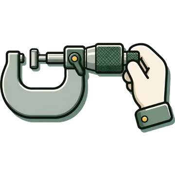
Outside micrometerOutside micrometer
Also called: micrometer, mic, standard outside micrometer, Digimatic micrometer
≡Standards, measuring range and accuracy
- Standard
- JIS B 7502 Geometrical product specifications (GPS) – Dimensional measuring equipment – Micrometers (the current JSA edition is 2026; Mitutoyo's explanation covers the 2016 edition)
- ISO 3611:2023 Design and metrological characteristics of micrometers for external measurements
- ASME B89.1.13 Micrometers
- Measuring range
- General The spindle travel is 25 mm. Ranges go in 25 mm steps: 0–25, 25–50, 50–75 mm ..., up to 0–2000 mm
- Selection examples To measure around 95 mm, use the 75–100 mm micrometer
- byMaker
- Mitutoyo 103-137/103-138 0〜25 / 25〜50 mm
- Teclock SSM-750/850 0–30 / 30–66 mm (digital, 10 mm per revolution)
- Resolution / graduation
- Standard Graduation 0.01 mm (the line width is about 1/5 of the spacing, so you can estimate by eye down to 0.001 mm)
- With vernier 0.001 mm
- Digital 0.001 mm (some models 0.0001 mm)
- Screw thread The standard screw has a 0.5 mm pitch. One thimble revolution advances the spindle 0.5 mm. Some models have a 2 mm pitch for rapid feed
- Accuracy (instrument error / maximum permissible error)
- Approach
- In JIS B 7502 (2016), "instrument error" became "indication error", and the most important indication error is the "full surface contact error J". The upper limit is set by the maximum permissible error J_MPE
- J is found by setting the zero point at the minimum measuring length using the constant-pressure device, then clamping a JIS B 7506 grade 0 or grade 1 gauge block across the entire measuring faces and subtracting the gauge dimension from the indicated value
- The main factors that determine accuracy are screw accuracy, flatness of the measuring faces, parallelism of the measuring faces, and frame rigidity
- byMaker
- Mitutoyo 103-137 (0–25 mm, 0.01 mm) J_MPE ±2 µm, parallelism 2 µm, flatness 0.6 µm, measuring force 5–10 N
- Teclock SSM-750 (0–30 mm, 0.001 mm digital) Indication error ±2 µm
- Approach
▦Types
With vernier (graduation 0.001 mm)
A vernier scale above the reference line on the sleeve lets you read 0.001 mm directly[3][8]1 source, for reference
Constant-pressure device types: ratchet stop / friction thimble (F-type) / ratchet thimble
The ratchet stop can be recognized by sound and feel, but it gives small clicking shocks and is not suited to one-handed operation. The friction thimble gives neither sound nor shock and can be used one-handed. The ratchet thimble can be used one-handed and confirmed by sound[3][9][7][6]
Special micrometers: point, blade, spline, single-ball and ball-type (pipe wall), U-shaped sheet-steel, disc (gear tooth thickness), thread (interchangeable anvils), V-anvil, ball-type tooth thickness, caliper-type inside, etc.
Interchangeable-anvil type (wide range)
[9]1 source, for reference
◎Part names and functions
| # | Name | English | Function |
|---|---|---|---|
| 1 | Frame | Frame | The U-shaped body. It holds the anvil and spindle. Its rigidity affects accuracy.[13][6][11] |
| 2 | Anvil | Anvil | The fixed measuring face. Often carbide-tipped.[13][6][11] |
| 3 | Spindle | Spindle | The movable measuring face, advanced and retracted by a screw. It is on the same axis as the anvil.[13][6][11] |
| 4 | Measuring faces | Measuring faces | Flatness and parallelism determine accuracy. Carbide is common; hardened steel if cost is the priority.[13][9] |
| 5 | Clamp (spindle clamp) | Spindle clamp | Locks the spindle. Loosen it for storage.[13][6] |
| 6 | Sleeve (barrel), reference line, and sleeve scale | Sleeve, index (fiducial) line, sleeve scale | A 1 mm scale above the reference line and a 0.5 mm scale below it.[13][6][11] |
| 7 | Thimble and thimble scale | Thimble, thimble scale | A scale dividing the circumference into 50 parts. One division is 0.01 mm.[13][6][11] |
| 8 | Ratchet stop (constant-pressure device) | Ratchet stop | Slips once a set measuring force is exceeded, evening out the force.[13][6][11] |
| 9 | Heat shield (insulating cover) | Heat insulating plate | Reduces heat transfer from the hand to the frame. Hold the micrometer here.[13][9][11] |
| 10 | Speeder (rapid-feed knob) | Speeder | A part for advancing the spindle quickly.[9][3] |
| 11 | ZERO/ABS, ORIGIN, HOLD buttons, display (digital types) | Buttons and display | Origin setting, relative zero, and hold.[13][9][11] |
◷How to read the scale
- On the sleeve, read the largest graduation visible to the left of the thimble edge (check both the 1 mm scale above and the 0.5 mm scale below)Example: the 7 mm line is visible but the 7.5 mm line is not → 7.0 mm[6][7][3]
- On the thimble scale, read the line that aligns with the sleeve reference line. If it is between lines, read the line below the reference lineExample: thimble 37 aligns with the index line → 0.37 mm[7][6][3]
- Add the twoExample: 7.0 + 0.37 = 7.37 mm (Mitutoyo). Niigata University's example reads to half a division by eye: 7.000 + 0.375 = 7.375 mm, and if the 0.5 mm line is visible, 7.5 + 0.375 = 7.875 mm[3][6]
- With vernier (0.001 mm): add in the order sleeve → thimble → vernier coincident lineExample: sleeve 6 mm + thimble 0.21 mm (index line between 21 and 22) + vernier 0.003 mm = 6.213 mm[3]
- Mechanical counter type: add the vernier's 0.001 mm to the 4 digits of the counterExample: 2.99 mm (counter) + 0.004 mm (vernier) = 2.994 mm[3]
- Guide for reading to 1 µm by eye: the graduation line is about 2 µm thick. Judge 1 µm and 2 µm from how the reference line and the thimble line overlap[13][3][14]
- Read the scale from the front, directly above the point where the reference line and the thimble line coincide[7][13][3]
Sleeve 7.0 mm + thimble 0.37 mm (37 divisions) = 7.37 mm
On the sleeve, the upper side has 1 mm graduations and the lower side has 0.5 mm graduations. The thimble divides 0.5 mm per revolution into 50 parts (1 division = 0.01 mm).
✋Usage steps
- Selection: choose by checking type, measuring range, and accuracy[3][7]
- Temperature soaking: let the micrometer and workpiece stabilize thoroughly at room temperature[7][3]
- Cleaning: clamp a sheet of white paper (lint-free) between the anvil and spindle measuring faces and pull it out gently to remove dirt. Also wipe chips off the spindle's outer surface[7][13][3][6]
- Operation check: turn the thimble through its full range and check for sticking or uneven movement[13]
- Zero-point check: turn the ratchet stop slowly to bring the measuring faces together and check that the thimble zero line aligns with the sleeve reference lineMitutoyo says to confirm with 1.5–2 turns of the ratchet and 3–5 applications of constant pressure (for 0–25 mm models). For models above 25 mm, use a micrometer standard rod. If it is off, turn the sleeve with a hook spanner to match, or use the offset as a correction value[7][13][6]
- When mounting in a stand, clamp the center of the frame and do not overtighten. Fix it at an angle where the scale can be seen evenly from above and below[7][3]
- Measurement: in the same posture and conditions as the zero-point check, lightly touch both measuring faces to the workpiece, turn the ratchet stop slowly 3–5 times, and readWhen approaching the workpiece, always turn the ratchet stop. Turning the thimble directly applies excessive measuring force and wears the screw, which degrades accuracy[7][6]
- Reading: read from the front. If you used the clamp, release it after reading[7][13]
- For long sessions, check the zero point periodically to allow for thermal expansion[13][14]
Printed from Kezuriba (kezuriba.net/en/gauges/outside-micrometer/)
!Common measurement mistakes and countermeasures
Heat from the hand
WhyIf you keep holding the frame bare-handed, it expands from the heat and the zero point shifts (Mitutoyo's experimental graph). The standard rod also lengthens from hand temperature
CountermeasureHold the heat shield. Hold the standard rod with gloves or support it lightly by its insulated part. A lengthened rod takes time to return to its original length[3][7]
Temperature difference between the micrometer and the standard rod
WhyIf they are kept in different places, their temperatures differ and the zero-point setting is off
CountermeasureKeep both in the same place for at least several hours before setting the zero point[3]
Excessive measuring force / turning the thimble directly
WhyIt damages the screw and also deforms the workpiece. Turning it roughly presses too hard on the anvil side
CountermeasureUse the constant-pressure device correctly. Make contact slowly[6][7][3]
Parallax
WhyThe coincident position of the scales appears to change with eye position
CountermeasureRead directly above the point where the reference line and the thimble line coincide[7][3][13]
Missing the 0.5 mm
WhyIf you overlook whether the 0.5 mm line below the sleeve is visible, you are off by 0.5 mm
CountermeasureCheck both the upper and lower scales (a micrometer head with 1 mm pitch avoids this misreading)[6][3]
Posture and support of large micrometers
WhySupport and posture make the frame sag, changing the zero point by several µm to tens of µm
CountermeasureSet the zero point in the same posture and support as the actual measurement[13][3]
Workpiece flattening with point or line contact
WhyClamping a ball or cylinder between flat faces deforms it elastically under the measuring force, so it reads smaller than it is (Hertz formula)
CountermeasureEstimate the deformation if necessary. Choose an instrument with a lower measuring force[3]
✓Care, storage, inspection and calibration
Care and storage
- After use, check for damage and clean; if water-soluble cutting fluid got on it, apply rust prevention[13][14]
- For storage, release the clamp and leave the measuring faces slightly apart (0.2–2 mm for E12024, 0.1–1 mm for E11003)[13][3]
- Avoid direct sunlight; store in a case in a place with little humidity, dust, or oil mist (do not leave it directly on the floor)[13][3]
- For long-term storage, apply micrometer oil to the spindle, and remove the battery from digital types[13]
- Do not drop or bump it. Do not shock the spindle[13][3]
Inspection and calibration
- Flatness of the measuring faces: place an optical flat on the anvil and count the red interference fringes under white light. One fringe ≈ 0.32 µm (e.g., 4 fringes is about 1.3 µm)[3]
- Parallelism of the measuring faces: wring an optical parallel to the anvil, apply constant pressure with the spindle, and count the fringes on the spindle side (e.g., 3 fringes → about 1 µm)[3]
- Indication error: clamp a gauge block across the entire measuring faces and find the full surface contact error J. Mitutoyo offers a gauge block set for micrometer inspection[3]
- For micrometers larger than 25 mm, the zero point is "checked" with a micrometer standard rod (this is not calibration)[9]
A micrometer follows the Abbe principle, placing the workpiece and the standard scale (the screw) on one line in the measuring direction, so it measures more accurately than a caliper (Mitutoyo). The three-wire method for the effective diameter of a thread (E = M − 3d + 0.866025P, best wire diameter 0.577P) is also done with a micrometer.
⇄Related instruments
📚Sources
Content without a mark is what agreed across two or more sources from different publishers. Procedures and cautions are summarized in Kezuriba's own words based on the sources, and the diagrams were drawn by Kezuriba. Accuracy values are manufacturers' published figures, not values from JIS tables.
- Japanese Standards Association (JSA), "JIS B 7502:2026 Geometrical product specifications (GPS) – Dimensional measuring instruments – Micrometers (bibliographic record)"
- ISO「ISO 3611:2023 Design and metrological characteristics of micrometers for external measurements」
- Mitutoyo, "Quick Guide to Precision Measuring Instruments (Catalog No. E11003(7), as of August 2024)"
- ASME「ASME B89.1.13 Micrometers」
- Mitutoyo, "Standard Outside Micrometer M110 103-137 Specifications"
- Niigata University, "Niigata University Faculty of Engineering, Technical Staff Training Text, Chapter 1: Workshop Measurement"
- Mitutoyo, "How to Use Micrometers Correctly and Cautions"
- Mitutoyo, "Outside Micrometer M310/M320 102-301 Specifications"
- Mitutoyo, "Mitutoyo Product Fundamentals (Bulletin No. 2180, Mitutoyo America)"
- Mitutoyo, "What Is Measurement (sokutei)? The Difference Between Sokutei and Keisoku"
- Niigata Seiki, "Digital Micrometer QEM29 Series Instruction Manual"
- Teclock, "General Catalog 5: Micrometers"
- Mitutoyo, "Check Points for Measuring Instruments (Catalog No. E12024)"
- Mitutoyo, "How to Use Interchangeable-Rod Depth Micrometers"