Measurement Error Basics: Abbe Principle, 20°C, Measuring Force, Uncertainty and Pass/Fail Decisions
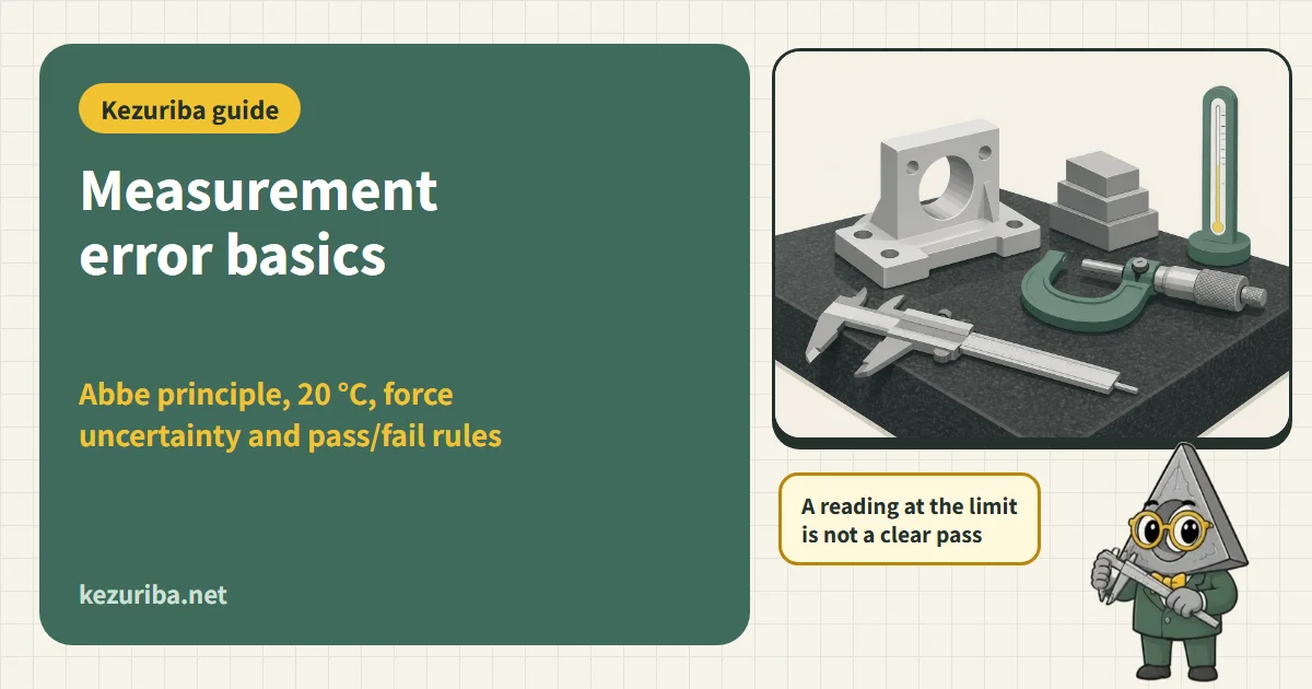
A reading right at the edge of the tolerance can't be called a pass, you know. The measured value has a spread too

Measure the same part with a caliper and get a 0.02 mm difference; the micrometer reading doesn't agree between morning and evening; a part that passed inspection is rejected by the customer. A measured value is always off somewhere among the instrument, the part, the person and the environment. This article divides the causes of error that matter on the shop floor into four: the Abbe principle, temperature (20°C), measuring force and parallax, and shows with numbers and calculators how far each one can throw a reading off. The second half covers measurement uncertainty and pass/fail decisions, gauge blocks and calibration traceability, Coordinate measuring machine (CMM) errors too. Finally, there is a checklist you can print and pin up in the measuring room.
Abbe Principle: Put the Scale and the Measured Point on One Line
The Abbe principle is the idea that "error is smallest when the object being measured and the scale (the reference) are lined up on one straight line in the measuring direction"[1][2][3]. A micrometer follows this principle: the screw of the spindle, which acts as the scale, and the line along which the part is clamped lie on one straight line. A caliper does not: the main scale and the point clamped by the jaws are apart. This is a major reason a micrometer can be more accurate.
Caliper: Tilt Becomes Error Directly (First-Order Error)
The slider has a little play, and the pressing force tilts the jaw slightly. If the distance from the scale to the measured point is h and the jaw tilt is a/ℓ, the error is f = h × a/ℓ . In Mitutoyo's example, with a tilt of 0.01 mm per 50 mm, measuring at the tip of an outside jaw 40 mm deep gives 0.008 mm[1]. With the same tilt, measuring near the base at h = 10 mm gives 0.002 mm, one quarter as much (worked example). The same is true of height gauges: Mitutoyo explains that measuring at h = 150 mm gives 1.5 times the error of h = 100 mm[1].
Micrometer: Tilt Acts as Its Square (Second-Order Error)
If the scale and the measuring line are on one line, a slight tilt gives an error of only L(1 − cos θ) ≈ L·θ²/2[1][4]. With a tilt of 0.01 mm/50 mm (θ = 0.0002 rad) and L = 25 mm, that is about 0.5 nm, four orders of magnitude below the caliper's 8 µm (worked example). However, if an inside micrometer is tilted in the hole, it reads longer by √(ℓ² + X²) − ℓ; with ℓ = 200 mm and one end displaced 10 mm, that is about 0.25 mm (worked example; the formula is from Mitutoyo[1]). This is why an inside micrometer is read at the minimum position when rocked in the axial direction of the hole, and at the maximum position when rocked in the diametral direction.
Bryan's Generalization: To CMMs and Machine ToolsOn CMMs and machine tools, the point you want to measure (the center of the stylus ball, the cutting edge) and the scale cannot be placed on one line. Bryan (1979) generalized the Abbe principle as: "the measuring system should be placed in line with the point to be measured; when that is impossible, either the guide must not move in angle, or the angular motion must be measured and corrected"[4][5]. This idea explains why error grows when the stylus is extended long to the side (Chapter 7).
Shop-floor tipsOn a caliper, clamp the part at the base of the jaws. For shapes reachable only with the tip, deep grooves and thin flanges, switch to a micrometer or a dedicated instrument. Read an inside micrometer at the minimum position when rocked in the axial direction of the hole and at the maximum position when rocked in the diametral direction, and a cylinder gauge at the turning point of the pointer.
Temperature: Dimensions Are Values at 20°C
Both the dimensions on drawings and the values in standards are values at 20°C. ISO 1 (JIS B 0680) sets the standard reference temperature for geometrical product specifications at 20°C. The 2022 revision made clear that 20°C is a value on the International Temperature Scale (ITS-90); the value of 20°C itself has not changed[6]. Thermal error is said to be one of the largest sources of error in machine tools and precision measurement, and one view is that 40–70% of machine tool error comes from heat[7] (for the machine's own thermal displacement, see the page on thermal displacement in maintenance).
When Materials Differ, the Expansions Do Not Cancel
The change in length is ΔL = α × L × ΔT (α: coefficient of linear expansion). When the instrument and the part differ in material and temperature, the apparent error is e ≈ L × {α(part) × (T(part) − 20) − α(instrument) × (T(instrument) − 20)}.[8][16] If you measure a steel part with a steel scale at the same temperature, both expand together and cancel out. This is why measuring steel parts with steel instruments has never caused trouble; with an aluminum part, they do not cancel[7].
Calculated with a linear expansion coefficient of 10.2×10⁻⁶/K for the caliper's main scale (stainless steel), 23.6 for A6061, 12 for S45C and 11.5 for the micrometer body (worked example). If a steel part and a steel instrument are at the same temperature, the deviation is small; it becomes large with aluminum, or when only the part is warm.
| Condition (100 mm) | Deviation from the 20°C dimension |
|---|---|
| Aluminum (A6061, α 23.6) together with the caliper (main scale 10.2) at 25°C | About +0.007 mm |
| Steel (S45C, α 12) together with the caliper at 25°C | About +0.001 mm |
| Steel at 35°C just after cutting, measured with a 20°C micrometer | About +0.018 mm |
| A 100 mm steel gauge block warmed by 1°C | +1.15 µm (about 4 times the grade 0 tolerance of ±0.30 µm) |
The top 3 rows are examples calculated from the caliper main scale value of 10.2×10⁻⁶/K[1] and the material values of the thermal expansion calculator; the last row is the value for steel gauge blocks in ISO 3650 (11.5×10⁻⁶/K)[26][9]. The h7 tolerance for φ100 is 35 µm, so measuring a 35°C part as it is uses up half the tolerance through temperature alone. Use the thermal expansion calculator (reading corrected to 20°C) to estimate the effect by entering the materials and temperatures.
Heat from the hand
If you keep holding a micrometer frame with a bare hand, it expands. In Mitutoyo's experimental graph, a 300 mm micrometer grows about 14 µm in 30 minutes, and even a 50 mm micrometer about 4 µm. A 200 mm standard rod held in a hand at 31°C grew about 18 µm in 10 minutes (values read from the graph; they are experimental values, not guaranteed values)[1]. Heat-insulating covers that make it harder for hand heat to reach the frame have even been patented[15].
Soak time
It takes time to bring temperatures into equilibrium. NIST gives the minimum time for gauge blocks placed on a soaking plate as 30 minutes for 0–10 mm, 100 minutes for 25–100 mm and 8 hours for 125–500 mm[9]. For a part after machining, in one example a plate with a 15°C temperature difference settled in 80–100 minutes when placed directly on a granite surface plate in a temperature-controlled room, and in about 200 minutes when held off the plate on 3 points[11]. Placing it directly on a surface plate, which carries the heat away, brings it to equilibrium sooner.
These figures come from sources with different conditions and are not meant to be compared on one scale. Use them to grasp the order of magnitude. The larger the temperature difference, and the larger the part or machine, the longer it takes.
Error That Remains After Correction
People tend to think "if I can't measure at 20°C, I can just correct by calculation", but the coefficient of linear expansion itself has uncertainty. It is at least 5% for steel used for gauge blocks and can reach 25% for other materials[7], and a material value is said to be hard to know more accurately than 0.5×10⁻⁶/K[4]. The further from 20°C you measure, the larger the error that remains after correction. In a NIST example, when a 250 mm block was measured at 20.5°C, the effect of the coefficient's uncertainty was 0.07 µm, but a temperature difference of only 0.1°C between the blocks made it 0.3 µm[9]. Rather than correcting, measuring close to 20°C with the part and the instrument at the same temperature is more effective.
Shop-floor tipsIf you measure aluminum on a summer afternoon, leave the part and the instrument on the same surface plate for at least an hour first. Hold the micrometer by the heat shield or mount it on a stand. For a dimension measured just after cutting, record the temperature and convert it to 20°C with the thermal expansion calculator before judging.
Measuring Force and Deflection
Micrometers have a ratchet stop, a friction thimble or a ratchet thimble, each a constant-pressure device, which slips once a set force is exceeded and evens out the measuring force. The ratchet stop can be recognized by sound and feel but is hard to use one-handed; the friction thimble works one-handed with no sound or shock; and the ratchet thimble works one-handed and can be confirmed by sound[1]. A study in engineering education that compared the operation of experts and beginners found that keeping the measuring force constant when bringing the spindle into contact matters more than reading the scale[14].
A caliper has no such constant-pressure device. The JIS handling precautions also call for measuring with an appropriate and uniform measuring force. Pressing hard tilts the slider and increases the Abbe error described in Chapter 1. The effect is especially large with inside jaws and long jaws, which are far from the reference surface[1]. This is also why a mechanism that signals by color or sound when a caliper reaches a set measuring force has been patented[13].
Part Flattening (Hertz Formula)
When a ball or cylinder is clamped between flat measuring faces, the contact area deforms elastically and reads smaller than the true size. For steel, a ball is δ₁ = 0.82 ∛(P²/D) µm, and a cylinder is δ₂ = 0.094 (P/L) ∛(1/D) µm (P: measuring force in N, D: diameter in mm, L: cylinder length in mm)[1]. Clamping a φ10 mm steel ball at 5 N makes it read about 1.1 µm smaller, and at 10 N about 1.8 µm smaller (worked example). NIST's gauge block handbook also has an example calculating the deformation where the stylus ball presses on the part in comparison measurement[9].
A worked example calculated from the Hertz formula in Mitutoyo's material (steel, Young's modulus 205 GPa). For a cylinder, δ₂ = 0.094 (P/L) ∛(1/D) µm (L: cylinder length in mm). Even at a measuring force of 5–10 N, as on a micrometer, a ball reads about 1 µm smaller.
Deflection of Large Micrometers
On a micrometer with a large measuring range, the frame sags under its own weight depending on how it is supported and its orientation, and the zero point shifts by several µm to more than ten µm. Mitutoyo's table includes an example of −22.5 µm for a 925 mm maximum measuring length when the support is changed[1]. Set the zero point with the same posture and support as in the actual measurement.
Shop-floor tipsOn a micrometer, turn the ratchet 3–5 times before reading (keep the number of turns the same). With a caliper, "touch lightly and do not push in". When measuring balls or pins, keep in mind that they read about 1 µm smaller.
Parallax and the Limits of Reading
If the graduation lines are not in the same plane, the position where the lines appear to coincide shifts when viewed at an angle (parallax). The step between the plane of the vernier and the plane of the main scale on a caliper is set by JIS at 0.3 mm or less (Mitutoyo's explanation)[1].
The smallest offset between two lines that the human eye can distinguish is said to be about 0.02 mm at the distance of distinct vision of 250 mm, and 0.01 mm even under good conditions[2]. Reading a 0.02 mm vernier is close to the limit of the eye. A digital instrument removes misreading, but resolution (0.01 mm) and accuracy (instrument error, maximum permissible error) are different things. Even for a caliper with 0.01 mm resolution, the permitted indication error is about ±0.02–0.03 mm, and the effects of Abbe error and measuring force remain as they are (see "Standards and accuracy" on each instrument's page).
Shop-floor tipsRead the scale from straight ahead. Use a digital or dial type where the scale is hard to read. Do not confuse "displayed to 0.01 mm" with "correct to 0.01 mm".
measurement uncertainty and pass/fail decisions
No matter how carefully you measure, a measured value has a spread. The number that expresses that spread is the measurement uncertainty. In the GUM (Guide to the Expression of Uncertainty in Measurement) procedure, the standard uncertainty of each factor is estimated from the scatter of repeated measurements (Type A) and from information such as calibration certificates, specifications and temperature (Type B), combined as the root sum of squares, and multiplied by a coverage factor k = 2 to obtain the expanded uncertainty U (about 95%)[17][18][16]. In comparison measurement of length, the main factors are the calibration value of the reference standard, repeatability, the temperature difference between the standard and the part, the difference in expansion coefficients, and wringing[16].
Shop Floor Examples
A report by the Japan Metrology Promotion Association gives an example from an automotive parts process. In a process measuring an outside diameter of φ19.02 (+0.043/+0.022) with a micrometer, combining a gauge R&R of 1.0 µm with the calibration uncertainty gives U ≒ 2.4 µm. In a process measuring an overall length of 60 (0/−1.5) with a caliper, the result was U ≒ 0.12 mm [19]. Against a tolerance of 21 µm, 2.4 µm is small, but with the caliper's 0.12 mm, a dimension with a tolerance of around 0.1 mm cannot be judged.
A Reading Right at the Edge of the Tolerance Is "Can't Say Either Way"
JIS B 0641-1:2020 (the same content as ISO 14253-1:2017) sets the rules for pass/fail decisions on the principle that when a measured value is close to a tolerance limit, uncertainty means it can be called neither conforming nor nonconforming. Conformance is proved by the supplier, who must show that the result is inside the acceptance zone, which is the tolerance narrowed inward by the amount of the uncertainty. Nonconformance is proved by the customer, who must show that the result is outside the rejection zone, which is the tolerance widened outward by the amount of the uncertainty. The rule is that the party making the claim bears the uncertainty[20][21][23]. To avoid disputes, the supplier and the customer should agree on the method of judgment in advance.
A diagram of the ideas in JIS B 0641-1:2020 (ISO 14253-1:2017). The supplier (the maker) proves conformance by showing that the result is inside the acceptance zone, the tolerance narrowed inward by g. The party proving nonconformance (the buyer) shows that it is outside the rejection zone, widened outward by g.
The width by which the tolerance is narrowed inward is called the guard band g . The old edition's default was g = U (k = 2), but the 2017 edition changed the default to "95% probability of conformance", to keep the risk constant regardless of the ratio of tolerance to uncertainty[21][22]. For a normal distribution, a one-sided 95% corresponds to a width of about 1.64u (u: standard uncertainty) (a calculated guide, not a value from the standard's tables). With the traditional g = U = 2u, the probability that a part exactly at the acceptance limit is actually nonconforming is at most 2.3%[22].
Two Risks
Passing a nonconforming part is false acceptance (consumer's risk), and rejecting a conforming part is false rejection (producer's risk). Widening the guard band reduces false acceptance but increases false rejection, where good parts are thrown away. Reducing the uncertainty reduces both and widens the acceptance zone[22][23]. In the US-style approach of a "4:1 accuracy ratio and 2% risk", there is an example that sets the acceptance limit at 0.77 times the tolerance[19].
The initial values are the example from the report above (φ19.02 +0.043/+0.022, U 2.4 µm). The measured value of 19.061 mm is inside the tolerance, but it exceeds the acceptance upper limit of 19.0606 mm, so it falls on the "cannot say it passes" side.
Pass/Fail of the Instrument Itself Also Includes Uncertainty
JIS B 0641-5:2021 is a standard that specifies how to treat the uncertainty of the test value when checking whether indicating instruments such as calipers, micrometers and dial indicators meet their maximum permissible error (MPE). B 0641-1 had asked that uncertainty also be considered when judging instruments, but it gave no specific treatment and interpretation varied on the shop floor, so this standard was created[24]. When you receive a calibration certificate, look not only at pass/fail but also at the uncertainty columnas well.
Shop-floor tipsFor a value right at the edge of the tolerance, re-measure it or measure it with an instrument of smaller uncertainty. Decide between a caliper and a micrometer for a given tolerance by the uncertainty of the process (including gauge R&R). Agree on the method of judgment with the customer in advance.
Gauge Block Grades and Calibration Traceability
The grades of gauge blocks (the JIS name is "block gauge") are K, 0, 1 and 2 (JIS B 7506:2004, based on ISO 3650:1998). For each grade, the "tolerance on length at any point (te)" and the "tolerance on variation in length (tv: variation within the surface)" are specified[25][26].
| Class | What differs (example for nominal size 10 mm or less) | Main uses |
|---|---|---|
| Grade K | te ±0.20 µm (same as grade 1), tv 0.05 µm (tighter than grade 0). Assumes the calibrated value is used | Reference for calibrating other gauge blocks by comparison measurement[26][10] |
| Grade 0 | te ±0.12 µm (the smallest), tv 0.10 µm | Testing the indication error J of micrometers (grade 0 or 1)[1] |
| Grade 1 | te ±0.20 µm, tv 0.16 µm | Same as above. Checking CMMs, calipers and micrometers[10] |
| Grade 2 | te ±0.45 µm, tv 0.30 µm | Checking instruments and setup in the workshop[10] |
The values are just one example row from Table 1 of JIS B 7506:2004 (Mitutoyo's explanation)[25]. The te of grade K is larger than that of grade 0 because it is a grade for which what matters more than being close to the nominal size is that the shape is good and the dimension is accurately known (that is, it is used with its calibrated value)[26]. Dealers' materials also have a guide table saying "K = reference and research use, 0 = inspection gauges and instrument checks, 1 = inspection, 2 = workshop use"[40], but this is not confirmed in the text of the standard.
When gauge blocks are wrung together correctly, the wringing film is only a few nm thick. It changes first because of hand heat, and then changes slightly over time[9][10]. In evaluations by public testing institutes, the uncertainty of wringing is estimated at 8 nm by optical interferometry, and at 0.02–0.03 µm in calibration of calipers and micrometers[31].
The Traceability Staircase
The unit of length, the meter, is defined by the speed of light, and the national standard is an iodine-stabilized He-Ne laser (wavelength 633 nm). The top-grade gauge blocks are measured by directly comparing them with the laser wavelength using an optical interferometer (interferometric measurement), and other gauge blocks are calibrated by comparing them with standard blocks on a comparator (comparison measurement). The calibrated gauge blocks are used to calibrate micrometers, calipers and CMMs, which then measure the product[27][2][30]. Every step carries an uncertainty, and it is larger the lower the step.
From left to right, each step is calibrated by the standard on the step above. The values are examples of expanded uncertainty (k = 2) and grow toward the lower steps (gauge blocks: Mitutoyo and JEMIC; micrometer and caliper: JCSS registered values of the Gunma Prefectural Industrial Technology Center; process example: the report of the Japan Metrology Promotion Association). The icons are illustrations generated with Canva.
Examples for each step (k = 2): for interferometric measurement of gauge blocks, Mitutoyo's best measurement capability is 30 nm for 100 mm or less, and for comparison measurement 60 nm[28]. JEMIC's JCSS calibration is 0.15 µm for 100 mm or less[29]. The JCSS registered values of a public testing institute (Gunma Prefecture) are 3.1 µm for micrometer calibration and 0.02 mm for caliper calibration (resolution 0.01 mm)[31]. Even with on-site calibration where the temperature varies, the thermal effect on the micrometer stayed at about 0.83 µm (standard uncertainty)[12].
Shop-floor tipsUse grade 0 or 1 for checking micrometers and grade 2 for setups in the workshop. Grade K is used with the values on its calibration certificate. On an instrument's calibration certificate, check the traceability (what it is linked to) and the uncertainty column.
Errors of Coordinate Measuring Machines
A CMM with three orthogonal axes has 6 errors per axis (positioning, straightness ×2, pitch, yaw, roll) and 3 squareness errors between axes, for a total of 21 geometric errors (commonly cited)[39][38]. Makers measure these and correct them in software. The one the user can manage most easily is temperature[11], and the other main factors are the stylus, how the points are taken and how the part is clamped[37].
- The measuring machine itself also expands: on a machine with a glass scale mounted away from the body, the error changed almost in proportion to room temperature, while on a machine with a metal scale attached directly to the guide surface it hardly changed. When the room temperature was changed from 20°C to 25°C, it took 5 hours or more for the machine's surface temperature to settle[32]
- Just after start-up and lighting: even in a room at 20±1°C, the coordinates drift by µm-level amounts just after start-up or after the lights are turned on. On one model, when the machine and lights were switched on together in the morning, the coordinates took until the evening to settle within 1 µm (with the lights off, it stabilized in about 1 hour)[33]
- MPE and the uncertainty of that measurement are different things: catalog values such as E0,MPE are values from a specified test. The uncertainty when measuring a given dimension of a given part is found by repeatedly measuring a calibrated workpiece closely resembling the part with the same procedure, and deriving it from the difference from the calibrated value and the scatter (ISO 15530-3)[36][37]
- Interim check: between periodic inspections, keep measuring a reference artifact at hand in the same way and watch for change (Annex A of JIS B 7440-2). There is a study that tried ball dimension gauges made of low-thermal-expansion ceramics and carbon tool steel[35][34]
How to choose a stylus, how to calibrate it and how to take points are covered on the CMM page.
Shop-floor tipsFor a measurement where 1 µm counts, switch on the machine and the lights the day before. Place the part directly on the surface plate to let its temperature equalize. For important dimensions, check the uncertainty with a calibrated workpiece.
Shop Checklist
It is summarized in 10 items so that you can print it out and pin it up in the measuring room.
- On a caliper, clamp at the base of the jaws: measuring at the tip adds error in proportion to h
- Bring the micrometer into contact with the ratchet: turn it 3–5 times and keep the number of turns the same
- Dimensions are values at 20°C: check the temperature difference between the part and the instrument. If the materials differ, estimate by calculation
- Allow time for soaking: 1–3 hours for a part with a 15°C temperature difference. Place it directly on the surface plate
- Do not hold with bare hands for long: heat shield, gloves, stand. Use tweezers for gauge blocks
- Read the scale from straight ahead: a 0.02 mm vernier is close to the limit of the eye
- Match the tolerance to the instrument: do not judge with a caliper if the tolerance width is narrower than about 0.1 mm
- Re-measure values right at the edge: measure with another instrument as well. Agree on the method of judgment with the customer
- Read the calibration certificate through to the uncertainty: not just pass/fail, but what it is linked to
- Start the CMM the day before: switch on the machine and the lights, and check against a reference artifact first thing in the morning
FAQ
- If a digital caliper displays to 0.01 mm, is it correct to 0.01 mm?
- No. Resolution and accuracy are different things. The permitted indication error is about ±0.02–0.03 mm depending on the model, and the effects of Abbe error, measuring force and temperature are added on top. See "Standards and accuracy" on each instrument's page.
- Can't I measure correctly without a 20°C room?
- If you measure a steel part with a steel (or stainless steel) instrument and both are at the same temperature, the error stays small even if you are somewhat away from 20°C. Be careful with materials with large expansion, such as aluminum, and with a part that is warm just after machining while the instrument is not. The thermal expansion calculator can estimate it.
- How do I estimate uncertainty?
- Combine the scatter of repeated measurements of the same part (Type A) with information such as the calibration uncertainty of the instrument and the temperature (Type B). The NITE introductory guide and gauge R&R results are a quick way in[17][19].
- I want to know how to read the instruments themselves.
- Caliper / Micrometer / Gauge block / Coordinate measuring machine (CMM) pages cover reading practice, how to use each one and common mistakes. If dimensions scatter, also see "Dimensions scatter or do not match" in the Machining Troubleshooting Encyclopediaas well.
Sources
- Mitutoyo, "Quick Guide to Precision Measuring Instruments" (E11003)
- Tokyo Metropolitan Industrial Technology Research Institute, "Accuracy and reliability of length measurement" [public institution report]
- Keyence, "Abbe principle"
- P. Schellekens et al., "Design for Precision: Current Status and Trends", Annals of the CIRP 47(2), 1998 [paper]
- J.B. Bryan, "The Abbé principle revisited: An updated interpretation", Precision Engineering 1(3), 1979 [paper, bibliographic record]
- ISO 1:2022 Standard reference temperature (JIS B 0680:2023) [standard]
- J.B. Bryan, "International Status of Thermal Error Research", UCRL-50285, 1967 [public institution report]
- T. Doiron and J. Stoup, "Uncertainty and Dimensional Calibrations", J. Res. NIST 102(6), 1997 [paper]
- NIST, "The Gauge Block Handbook" (Monograph 180) [public institution report]
- NPL, "Good Practice Guide No. 149": Care and Use of Gauge Blocks [public institution report]
- Oita Industrial Research Institute, "Study of measurement error due to the temperature environment in coordinate measuring machines" (1986) [public institution report]
- Gunma Prefectural Industrial Technology Center, "Establishment of on-site calibration methods for calipers and micrometers" (2023) [public institution report]
- Japanese Patent Application Publication 2015-025777 (Patent No. 6224372), "Measuring instrument" [patent]
- Takeo and Xia, "A study on teaching practice for keeping the measuring force of outside micrometers constant", Engineering Education 61(6), 2013 [paper]
- US 8,245,413 B2, "Heat insulating cover and micrometer" [patent]
- National Institute of Technology and Evaluation (NITE), "Guide to JCSS uncertainty estimation (block gauges)" [public institution report]
- NITE, "Introductory guide to uncertainty" [public institution report]
- General Building Research Corporation of Japan, "The meaning of measurement uncertainty" [public institution report]
- Japan Metrology Promotion Association, "FY2011 research report on the utilization of measurement uncertainty" (2012) [public institution report]
- JIS B 0641-1:2020 Decision rules for verifying conformity or nonconformity with specifications (preview) [standard]
- ISO 14253-1:2017 (preview on iTeh) [standard]
- JCGM 106:2012, "The role of measurement uncertainty in conformity assessment" [standard]
- H. Nielsen, "ISO 14253-1 Decision Rules"
- JIS B 0641-5:2021 Uncertainty in verification testing of indicating measuring instruments (preview) [standard]
- Mitutoyo, "About the 2004 edition of JIS B 7506 'block gauges'"
- ISO 3650:1978 Gauge blocks (preview on iTeh) [standard]
- Bito, "Calibration methods of gauge blocks and their uncertainty", AIST Bulletin of Metrology 4(1), 2005 [public institution report]
- Mitutoyo, "On improving calibration uncertainty"
- Japan Electric Meters Inspection Corporation (JEMIC), "JCSS calibration of block gauges" [public institution report]
- Yokogawa Electric, "Block gauges (JCSS calibration)"
- Gunma Prefectural Industrial Technology Center, "Uncertainty evaluation for renewal of ISO/IEC 17025 and JCSS registration" (2016) [public institution report]
- Oya, "Effect of the temperature environment on the accuracy of coordinate measuring machines", Transactions of the Japan Society of Mechanical Engineers, Series C 65(631), 1999 [paper]
- Gunma Prefectural Industrial Technology Center, "Study on the effect of ambient temperature on 3D measurement accuracy" (2019) [public institution report]
- Wago et al., "A study of interim check methods for coordinate measuring machines", Journal of the Japan Society for Precision Engineering 79(3), 2013 [paper]
- JIS B 7440-2:2013 (preview) [standard]
- ISO 15530-3:2011 (preview on iTeh) [standard]
- NPL, "Good Practice Guide No. 130": Measurement Uncertainty of Coordinate Measuring Machines [public institution report]
- H. Schwenke et al., "Geometric error measurement and compensation of machines — An update", CIRP Annals 57(2), 2008 [paper, abstract]
- "Efficient Method for Identifying Key Errors Based on 21-Geometric-Error Measurement…", Applied Sciences 14(7), 2024 [paper]
- MISUMI, "Block gauges" product page (a dealer's guide to uses)
More articles
 NC
NCNC Lathe Programming Basics: A Browser Simulator and Graded Exercises
 Industry
Machining for the Semiconductor Industry: Types of Machining, Large to Small Parts, Major Japanese Companies, Machine Tools and Cutting Tools, New Technologies, How to Enter
 Gears
Gears