GEAR SIMULATORGear Meshing & Generation
Why do involute gears run so smoothly, and how is the tooth profile cut? In your browser, you can run both the meshing of two gears and the generation of teeth by a hob. The tooth profiles are drawn by calculation, so they change on the spot when you change the tooth count, profile shift, or pressure angle.
The contact point
always moves along
a single line!

⚙Watch the meshing
Green gear 1 drives brown gear 2. The red dot is the contact point between the teeth. It moves at a constant speed along a single straight line (the line of action) tangent to both base circles. In the orange section two pairs of teeth are in mesh at once; in the green section only one pair carries the load.
With fewer teeth
With 11 teeth, the start of contact falls outside the base-circle tangent point T1 (interference). This gear is also undercut when it is cut.
With profile shift
Shifting gear 1 by x = 0.4 thickens and strengthens the root and removes the interference. In exchange, the centre distance grows slightly.
With a wider centre distance
Backlash increases and the contact ratio drops. Even so, the speed ratio does not change, which is the strength of involute gears.
▶Watch the generation (how hobbing works)
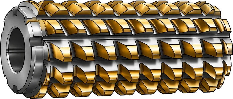
A cross-section of the hob's teeth along its axis is a rack: a row of straight-sided teeth. The hobbing machine turns the hob and rotates the workpiece so that the rack meshes with the gear. The traces left by the tool overlap and leave an involute tooth profile that the tool itself never had. Press "Cut" to watch.
Undercut
Cutting 11 teeth, the cutter tip scoops out the root and the base of the tooth becomes thin: the part cut inside the red dashes (the theoretical profile).
Preventing it with profile shift
Moving the cutter outward (x = 0.4) avoids the undercut even with the same 11 teeth. Shift too far and the tip becomes pointed instead (try it with 8 teeth).
Protuberance hob
A gear that will be ground after hardening is cut slightly deeper at the root first, so that the grinding wheel does not leave a step at the root.
ATerms on this page
- Base circle
- The circle from which the involute curve is generated. Unwind a string wrapped around the circle, and the end of the string traces an involute.
- Pitch circle
- The circle on which two gears roll against each other without slipping. Its diameter is module × tooth count (the pitch circle in mesh changes slightly when you change the profile shift or the centre distance).
- Line of action
- The straight line tangent to both base circles. The contact point of involute gears always moves along this line, and the force pushing on the teeth acts in the same direction.
- Pressure angle
- The angle between the line of action and the tangent to the pitch circle. 20° is today's standard; 14.5° survives in older standards and replacement parts.
- Contact ratio
- The average number of tooth pairs in mesh at the same time (length of action ÷ normal pitch). It must be greater than 1, or the rotation is interrupted. Real gears have errors and deflection, so leave some margin.
- Backlash
- The gap between meshing teeth. It is provided by widening the centre distance, cutting the teeth thinner, and so on. At zero, thermal expansion or errors can make the gears bind.
- Generation
- A method of cutting the tooth profile by moving the tool and the workpiece together as if a gear were meshing with a rack. Most hobbing, gear shaping and gear grinding work this way.
- Undercut
- When the tooth count is low, the tool tip digs into the root during generation. For a standard 20° pressure angle gear, it occurs below 17.1 teeth.
- Profile shift
- Cutting with the tool moved away from (or toward) the gear centre. It prevents undercut even at low tooth counts and is also used to adjust the centre distance.
The tooth profiles are drawn by calculating the area swept as a rack-shaped tool is moved in small steps and removes material (they are not drawn from the involute equation, so undercut and the protuberance relief come out of the tool shape). The formulas for contact ratio, centre distance and pressure angle are the same as in the technical references listed below, and give the same values as this site's spur gear calculator. Backlash shows only what the wider centre distance adds and does not include the tooth thickness tolerance.
⚙Related
📚Sources
- KHK (Kohara Gear Industry), Gear Technical Reference (web) 3.2 Involute curve
- KHK (Kohara Gear Industry), Gear Technical Reference (web) 3.3 Meshing of involute gears
- KHK (Kohara Gear Industry), Gear Technical Reference (web) 3.5 Undercut
- KHK (Kohara Gear Industry), Gear Technical Reference (web) 3.6 Profile shift of gears
- KHK (Kohara Gear Industry), Gear Technical Reference (web) 4.1 Dimension calculations for spur gears and racks
- KHK (Kohara Gear Industry), Gear strength: bending strength calculation formulas for spur and helical gears (transverse contact ratio formula, Table 10.1)
- Kyoiku Gear (KG), Technical Reference (PDF, 176 pages: gear basics, profile shift, contact ratio, tooth thickness measurement, accuracy, calculations for various gears)