HobDesign, Selection and Troubleshooting
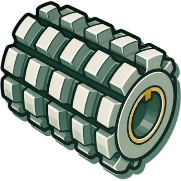
A hob is a milling cutter made by providing cutting edges on a worm; it generates the tooth profile by rotating the workpiece gear in step with the hob rotation and feeding along the helix (lead) direction. Because everything except the feed is rotary motion, it is more productive than other gear cutting tools. It is used from pre-machining to finishing of spur and helical gears, and there are special hobs for racks, sprockets, splines, and worms, as well as carbide hobs used after heat treatment.
✎How to Design and Select
Open a heading to see its contents. When printed, everything is shown open.
Hob cutting principle and setting angle
3
- A hob is a milling cutter with cutting edges cut into a worm. Because everything except the feed is rotary motion, it is more productive than other gear cutting tools.[1]One source / reference
- As the hob rotates, the teeth on the thread surface appear one after another on the generating plane, onto which a straight-moving rack is projected. The workpiece gear is rotated so that it meshes ideally with this rack, and at the same time the generating plane is fed along the helix (lead) direction of the gear, so the gear is generated.[1]One source / reference
- Hob setting angle: for spur gears, tilt the hob by its lead angle γ. For helical gears, it is β−γ if the gear helix and the hob lead have the same hand, and β+γ if they have opposite hands.[1]One source / reference
How to determine the basic rack (module, pressure angle, tooth depth)
7
- Once the gear's basic rack is determined, the tool's basic rack is determined. The tool tooth form is expressed by addendum hkc, dedendum hfc, tooth thickness Sc, and cutting depth hc.[1]One source / reference
- JIS (pressure angle 20°): tool hkc 1.25m, hfc 1.25m, Sc 0.5πm, hc 2.25m (gear side hkg 1m, hfg 1.25m, Sg 0.5πm).[1]One source / reference
- DIN (20°): tool hkc 1.1m–1.3m, hfc 1.1m–1.3m, Sc 0.5πm, hc 2.1m–2.3m.[1]One source / reference
- Pre-shaving (20°): tool hkc 1.35m, hfc 1.25m, Sc 0.5πm−Ss, hc 2.35m (gear side Sg 0.5πm+Ss).[1]One source / reference
- Fellows stub (20°): tool hkc 1.25m₂, hfc 1.25m₂, Sc 0.5πm, hc 2.25m₂. The module is written m₁/m₂, where m₂ is the module used to calculate the tooth depth. AGMA STUB: hkc 1m, hfc 1m, hc 1.8m. SYKES (double helical): hkc 1.15m, hfc 1m, hc 1.95m.[1]One source / reference
- Recommended shaving allowance (on tooth thickness): 0.05–0.08 for mn ≤ 2.25, 0.06–0.10 for 2.25 < mn ≤ 3.5, 0.08–0.12 for 3.5 < mn ≤ 5, 0.10–0.15 for 5 < mn ≤ 12.[1]One source / reference
- The hob pressure angle can be designed differently from the reference pressure angle (profile shift design: changing the gear cutting PCD and designing the hob rack profile with a pressure angle different from the reference). In a Nachi-Fujikoshi case, a tooth-surface flaw at the root on the trailing side that appeared with a 20° pressure angle hob was eliminated by a hob profile-shifted to 15° (dry, climb).[2]One source / reference
Choosing the profile modification (protuberance, semi-topping)
5
- Cutter profile symbols (per JIS B4350): P = pre-shaving profile (tooth thickness is reduced by the shaving allowance and the addendum is made taller; generally applied to gears with few teeth). PP = protuberance at the tooth tip. PS = with semi-topping (chamfer). PSP = with both protuberance and semi-topping. S-TOP = semi-topping profile for finishing. For pre-grinding: (PG)(PGP)(PGS)(PGSP).[1]One source / reference
- Symbol order: first P (Pre-shaving) or PG (Pre-grinding), second S (Semi-topping), third P (Protuberance). For finishing, S-TOP only.[1]One source / reference
- A hob with protuberance (knob hob) is for pre-machining gears to be finished by shaving or grinding. It keeps the tip of the shaving cutter (grinding wheel) from interfering with the root fillet of the workpiece gear during shaving (grinding).[1]One source / reference
- The protuberance size is normally determined from the shaving allowance (grinding allowance) and the effective working depth of the mating gear.[1]One source / reference
- Causes listed for insufficient contact length of the workpiece are: insufficient hob tooth depth, excessive hob tip radius, poor hob tip protuberance shape, and design error.[3]One source / reference
Chamfer size of chamfering hobs and sharing a hob
4
- A chamfering hob is used when a chamfer is wanted on the tooth tips of the gear during hobbing; it has a chamfering section at the root of the hob.[1]One source / reference
- When a chamfering hob is shared, the gear chamfer size must be calculated considering the number of teeth and profile shift coefficient of the shared gears and, if there is later machining, the finishing allowance.[1]One source / reference
- Example: when a hob designed for a standard spur gear with 35 teeth (x = 0, C = 0.1m) is shared with a profile-shifted gear, the chamfer size grows with more teeth and with a more negative profile shift coefficient (m = 1, α = 20°).[1]One source / reference
- Changing the hob setting angle reduces the tooth thickness of the workpiece gear. If the hob infeed is reduced to compensate, the tooth-tip chamfer size with a chamfering hob is reduced.[4]One source / reference
Constraints from the number of teeth and profile shift coefficient of the workpiece gear
2
- With fewer teeth, fewer hob teeth cut and the chip thickness increases. For this reason multi-start hobs cannot be used for gears with few teeth.[1]One source / reference
- When the profile shift coefficient is 0 or less and the number of teeth decreases, undercut occurs easily (Fig. 4: with 10 teeth, undercut occurs at profile shift coefficients of −0.5 and 0).[1]One source / reference
How to choose the number of starts
7
- An n-start hob indexes n pitches per hob revolution, so it can machine at n times the speed of a single-start hob. However, the cutting load per hob tooth increases and the feed must be lowered slightly, so efficiency cannot simply be raised by a factor of the number of starts.[1]One source / reference
- With more starts, fewer cutting edges finish each gear tooth and the profile polygonal error grows (profile polygonal error is proportional to the square of the number of starts). Cutting load also increases, and if the hobbing machine is not rigid, helix (lead) deviation tends to occur. Nidec's material also says that increasing the number of starts tends to lower hobbing accuracy by one grade and makes chipping more likely.[1][5]
- With a multi-start hob, chips are thicker and shorter, and the contact position between the chip and the rake face moves away from the cutting edge, which suppresses edge recession and breakdown and improves life. If machining at the same output, cutting speed and feed can be lowered, so even longer life can be expected (however, without a rigid hobbing machine the effect may not be fully obtained).[1][5]
- Mitsubishi Materials' guideline: the general limit for multi-start hobs is 'number of workpiece teeth ÷ 6 or less' (example: with 12 teeth, up to 2 starts) and a hob lead angle of 10° or less. The track record on production lines is up to 6 starts.[1]One source / reference
- Nidec's guideline: '(number of workpiece teeth ÷ number of starts) ≥ 9'; the limit also varies with the hobbing machine. With a multi-start hob, 'number of workpiece teeth ÷ number of starts' should in principle not divide evenly. When increasing the number of starts, make sure that 'number of starts × axial feed rate (mm/t.rev.)' does not exceed 8.[5]One source / reference
- Nidec's criteria for number of starts and gashes: workpiece teeth NT20 or less → 1 start 10–12 gashes (finishing, PS), 2 starts 12–14 gashes (PS). NT20 or more → 1 start 10 gashes (finishing, PS), 2–3 starts 12–14 gashes (PS), 4–5 starts 14–17 gashes (PS).[5]One source / reference
- Reducing the number of starts: hobbing accuracy (profile, pitch) improves, hob accuracy itself is easier to secure, and the hob price falls. On the other hand, it is harder to raise machining output, and high-speed cutting becomes unavoidable, which is bad for tool wear. Increasing the number of starts raises the hob price.[5]One source / reference
How to choose the number of gashes
4
- Increasing the number of gashes: hobbing polygonal profile error decreases. Feed can be increased and higher output can be expected (Nidec: hob spindle cutting force is reduced somewhat and axial feed can be raised somewhat). The accuracy degradation of multi-start hobs can be eased.[1][5]
- Increasing the number of gashes reduces the effective cutting width (sharpenable width) for the same hob outside diameter. Nidec also cites lower strength of the cutting edge itself and higher sharpening cost and hob price.[1][5]
- Reducing the number of gashes: the sharpenable width increases and the number of sharpenings increases (for similar wear). Chips become thicker, and hob wear does not increase and even decreases. On the other hand, hob spindle cutting force rises somewhat, helix (lead) accuracy worsens somewhat, and polygonal profile error grows.[5]One source / reference
- Normally the standard dimension (number of gashes) in the catalog is used.[1]One source / reference
How to choose outside diameter and overall length
5
- The outside diameter normally follows the standard catalog dimension. If there is interference with the workpiece (shoulder gear) or the hobbing machine, choose a diameter that does not interfere.[1]One source / reference
- A smaller diameter allows higher spindle speed at the same cutting speed, so higher productivity can be expected. Points to watch: the effective cutting width becomes smaller and the lead angle becomes larger. The bore (hob arbor diameter) may need to change.[1]One source / reference
- The overall length normally follows the standard catalog dimension. In mass production, a longer hob widens the shiftable range and increases the number of parts per regrinding. The number of parts increases with the ratio of the shift range, not the length ratio, so the gain exceeds the length ratio. The effect is larger for workpieces with a small shift range, that is, many teeth or a large module.[1]One source / reference
- When changing the overall length, check the hobbing machine specification and interference during shifting. Both the shift start and end positions must be within the machine's shiftable range.[1][6]
- The active length of the hob's outer-periphery cutting edges varies with the gear diameter, helix angle, hob outside diameter, hob lead angle, and hobbing method (example: charts of active length for β = 30°, 2-start hob, climb, for gear outside diameters and hob outside diameters d0 of 60–115).[7]One source / reference
How to choose rake angle and gash lead
5
- The rake angle is normally 0°. A hob is finished so that the theoretically correct profile appears when the rake face is ground radially, so sharpening with a rake angle or a crowned (convex) face causes errors in the pressure angle and profile (profile errors of the workpiece gear).[1][8]
- A rake angle is sometimes added to improve cutting action, but the effect varies by case. A rake angle makes crater wear shallower, but the deepest point of the crater tends to move closer to the edge.[1]One source / reference
- In tests of TiN-coated hobs, the effect of rake angle is marked at a cutting speed of 100 m/min but not at the higher speeds of 130 and 160 m/min. The larger the rake angle, the shallower the crater depth (KT), but the shorter the distance (KM) from the deepest part of the crater to the tooth tip cutting edge, which causes recession of the tooth tip cutting edge.[1]One source / reference
- Nidec states the rake angle on the drawing and in the marking (nothing is stated for a 0° rake angle).[9]One source / reference
- Gash lead: when the lead angle is large, ideally the lead is applied normal to the tooth as a tool shape, but regrinding becomes harder. It is effective (necessary) when the cutter machines at the same timing along the entire length, as with a rack hob.[1]One source / reference
Choosing grade and coating (hob)
8
- Mitsubishi Materials' guideline: for material, KMC3 for general machining, KVC5 for high-speed wet machining, and DH01B for high-speed dry machining. For coating, Violet or Ti coating for medium/low-speed wet machining, DP coating for high-speed dry machining, and GV40 or DP coating with rake-face coating for ultra-high-speed dry machining.[1]One source / reference
- Mitsubishi Materials' cutting speed guide (figure): wet, no rake-face coating: TiN/Violet (about 50–120 m/min); wet, with rake-face coating: GV40 (about 100–150 m/min); dry, no rake-face coating: DP (GV50) (about 100–180 m/min); dry, with rake-face coating: GV40 (about 100–200 m/min), DP (GV50) (about 200–300 m/min).[1]One source / reference
- Nidec selection map (hob, material): at about 50 m/min or less and low hardness, SKH55, SKH51, MAC B. Up to 150 m/min, MACH11, MACH7, MACH5 (wet), MAC C (wet); for high hardness (non-heat-treated steels of HB220 or more, etc.), MAC B (wet), MACH13. At 150–300 m/min, GRANMET SF and MACH11 for carburizing steel (up to HB180), MACH11 for higher hardness, and MACH13 for still higher hardness.[10]One source / reference
- Nidec selection map (hob, surface treatment): up to 100 m/min and low hardness, Black Dynamic; up to 150 m/min, Super Dry I and II; up to 200 m/min, Super Dry III (full coat); up to 300 m/min and HB300, MightyShield Σ (full coat).[10]One source / reference
- Nidec GRANMET SF: excellent heat resistance (hot hardness) and wear resistance, intended to counter crater wear. Nidec says it supports cutting speeds of 300 m/min and above, comparable to carbide hobs. In a case (m2.25, 46 teeth, PA17.5°, helix angle 23°, SCM415, 3 starts, 16 gashes, Super Dry III, 400 m/min, axial feed 1.7 mm/rev, dry, no shift, 40 pieces; hob materials listed as GRANMET SF and MACH11) it is reported as '4× cutting length' and '40% less wear'.[11]One source / reference
- Nidec MACH13: a grade with improved chipping resistance for countering chipping, usable both wet and dry. Nidec positions SKH55 = general-purpose (wet), MACH5 = standard (wet), MACH7 = standard (dry).[12]One source / reference
- In dry hobbing, cutting oil no longer provides lubrication, cooling, or chip evacuation, so dry hobs need high lubricity, high heat resistance, and high chip evacuation that does not trap chips. According to Nachi-Fujikoshi's analysis, the cutting temperature in dry hobbing of carburized material reaches about 800°C at 150 m/min and about 900°C at 250 m/min, so the base material and coating are considered to need heat resistance above 900°C.[2]One source / reference
- With rake-face coating, crater wear, in which hot chips rub and gouge the rake face, develops more slowly. If the rake face always has coating through regrinding and recoating, stable high-speed dry hobbing at V = 200 m/min or more is possible (Nachi-Fujikoshi Hyper DuAl hob).[2]One source / reference
Choosing the accuracy grade
3
- For pre-machining, grade A is normally used. For hobbing-finished work, grade AA is recommended.[1]One source / reference
- Quality grades normally obtained by hobbing are about DIN 9–12 (JIS 5–7 and below); DIN 7 and 8 (JIS 3 and 4) are obtained only with excellent workmanship. If the final machining is heat treatment, quality drops by 1–2 grades depending on the working method. The comparison between DIN and AGMA/JIS is rough.[1]One source / reference
- Some makers, including for worm wheel hobs, produce to DIN 3968 quality classes B to AAA (SAACKE).[13]One source / reference
Choosing cutting speed and feed
2
- For hobbing small and medium module gears, 50–250 m/min is the practical range. The applicable range varies with workpiece material, hob grade, and coating.[1]One source / reference
- Feed is generally expressed as the distance the hob moves per workpiece revolution. It strongly affects the finished surface, so use a value appropriate to the application. Guide: finishing 0.8–2.0, before shaving 2.0–4.5, before grinding 2.0–6.5 (mm/rev).[1]One source / reference
Choosing the shift (range, amount, direction, method)
7
- Maximum hob wear occurs on the teeth on the entry side (roughing region), and that wear amount determines when to regrind. So the hob setting position is moved in the hob axis direction at fixed cutting-length intervals (shifting), spreading maximum wear over every tooth and machining as many gears as possible before regrinding.[1][7]
- Set three items of hob shifting correctly: hob shift range (set the shift position accurately to avoid ungenerated stock and hob breakage), hob shift amount (match to workpiece, hob, and machining conditions), and hob shift direction (the direction in which new cutting edges always come to the generating side).[6]One source / reference
- Total shift is found from the hob length needed to machine the gear (Fig. 10 shows the hob length needed on both sides of the hobbing machine's centerline, by number of teeth and helix angle. A: approach side, B: run-out side).[1]One source / reference
- Comparison of shift methods: Every-time shift (every workpiece) = wear spots are spread, but shift time affects cycle time. Intermittent shift (every few workpieces) = cycle time can be shortened, but too many workpieces between shifts risks abnormal wear. 1-pitch shift (every hob pitch) = not affected by hob runout, so tooth thickness and profile are stable, but abnormal wear occurs if too many workpieces are cut between shifts and tool life is short if too few. Multi-shift (repeat with the start position offset) = wear spots are spread, but tooth thickness and profile may change due to hob runout.[6]One source / reference
- Shift direction: one-way shift = shift in the direction where new cutting edges always come to the generating side. Life ends when the shift end is reached, or the hob is returned to the start position. Machining accuracy is favorable but returning takes time. Reciprocating shift = used while returning at the shift end. Adopted when tool life is long; no return time is needed, so cycle time is shorter.[6]One source / reference
- On NC hobbing machines, the shift range is calculated automatically by the machine's conversational program. Strictly, the active length of the hob's outer-periphery cutting edges is calculated by the toolmaker from each hob and gear data.[7]One source / reference
- Nidec's formula for the shift amount per shift moves the cutting edge at the generating center to positions ① → ② → ③ …; it is not a formula for the optimum shift amount that optimizes wear or stabilizes machining accuracy.[6]One source / reference
Conventional cutting and climb cutting
2
- Climb is a gear cutting method in which hob rotation and feed direction are opposite at the contact point between hob and gear material (the same feed direction as down-cut milling). Conventional corresponds to up-cut.[2][1]
- Comparison: flank wear: conventional ×, climb ○; chip jamming: conventional ×, climb ○; finished surface roughness: conventional ○, climb △.[1]One source / reference
Special hobs (rack, sprocket, carbide, worm wheel)
6
- Rack hob: a hob that machines the rack of an automotive steering system (rack and pinion). Rack accuracy affects steering feel, so high accuracy is required. Features: tooth shape accuracy such as tooth thickness and pressure angle within a few μm. It has 20–50 teeth, and cumulative pitch error is within 20 μm. An unequal-tooth-thickness rack hob varies the tooth thickness and pitch of each tooth by a few μm.[1]One source / reference
- When the cutter machines at the same timing along the entire length, as with a rack hob, a gash lead is effective (necessary).[1]One source / reference
- Sprocket hob: there is a dimension table for chain pitch (CP) 6.35–38.1, and a standard ASA type I tooth profile (roller chain nominal numbers 40–120). For ASA type II, Cl = 0.[1]One source / reference
- Carbide hob: a solid type that can be made with a smaller diameter, more gashes, and more starts. It uses an (Al,Ti)N coating (Miracle coating) with excellent high-temperature properties, ideal for dry machining, enabling ultra-high-speed machining above 300 m/min (Mitsubishi Materials). Control of shrinkage behavior during sintering and grinding technology make it possible to produce high-accuracy solid carbide hobs.[1]One source / reference
- In the process sequence, carbide hobbing is placed in the finishing process after heat treatment (gear manufacturing process diagram). 'Carbide hob: high-hardness materials, large gears' is listed as a finishing method for external gears.[1]One source / reference
- Worm wheel hob: SAACKE makes them from module 0.5 to about 20 mm, outside diameter φ32–200 mm, and lead angles up to 45°, and says it simulates the tooth contact (contact pattern) at the technical design stage.[13]One source / reference
÷Formulas
Hob calculator (lead angle, shift amount, feed marks)
Lead angle = sin⁻¹(m × Zw / (outside diameter − addendum × 2)). The shift amount is the amount to move the cutting edge at the generating center to the next tooth position; it is not the amount that optimizes wear (Nidec). Feed marks: root fR = R − √(R² − S²/4) (R = hob radius), tooth flank fS = fR × sin α. The initial value of the addendum is 1.25m.
Hob lead angle
Lead angle = sin⁻¹(module × number of starts / (hob outside diameter − hob addendum × 2))[1]1 source · reference
- Module
- Hob module
- Number of starts
- Number of hob starts
- Hob outside diameter
- mm
- Hob addendum
- Hob addendum (mm)
Hob setting angle (helical gear)
Hob and gear have the same hand: φ = β₀ − γ / opposite hands: φ = β₀ + γ[1]1 source · reference
- φ
- Hob setting angle
- β₀
- Gear helix angle
- γ
- Hob lead angle
Worked Example For spur gears, setting angle = γ (Fig. 3)
Shift amount per shift (straight-gash hob)
l = Zw × m × π / (cos γ × i) (Nidec notation: ℓ = Mn × π × z / (cosγ × i))[1][6]
- l (ℓ)
- Shift amount (mm)
- Zw (z)
- Number of hob starts
- m (Mn)
- Module (Nidec uses the hob normal module)
- γ
- Hob lead angle (deg)
- i
- Number of hob gashes
Worked Example Nidec: Mn 1.5, γ 3°, z 3, i 16 → ℓ = 1.5×π×3÷cos3.0×16 = 0.88
Shift amount per shift (helical-gash hob)
l = Zw × m × π × cos γ / i[1]1 source · reference
- l
- Shift amount (mm)
- Zw
- Number of hob starts
- m
- Module
- γ
- Hob lead angle (deg)
- i
- Number of hob gashes
Effective hob shift length
S = l − ( K + 2a ), K = k + k0, a ≈ π / 2 m, k0 = Ca·cosβ / tanαn·cosτ[7]1 source · reference
- S
- Hob shift range (mm)
- l
- Hob tooth length (mm)
- K
- Active range of the hob cutting edges
- k
- Active length of the hob outer-periphery cutting edges from the generating center (read from chart)
- k0
- Profile generating range from the generating center of the hob (one side)
- a
- Hob allowance length
- Ca
- Hob cutter addendum
- αn
- Tool pressure angle (normal)
- β
- Gear helix angle
- τ
- Hob setting angle
Worked Example Gear m2.25 PA14.5° NT25 β30° D0 70, hob d0 90, 2 starts, tooth length l 130 → k=23, k0=13, K=36, a=3.5, S = 130 − (36 + 7) = 87 (mm)
Feed mark height
Root: fR = R − √(R² − S²/4), tooth flank: fS = fR × sinα[1]1 source · reference
- fR
- Feed mark height at the gear root
- fS
- Feed mark height on the gear tooth flank
- R
- Hob radius (mm)
- S
- Feed (mm/rev)
- α
- Pressure angle (deg)
Feed for an n-start hob
Sn = (0.7)^(n−1) · S[1]1 source · reference
- Sn
- Feed for an n-start hob (mm/rev)
- S
- Reference feed (mm/rev)
- n
- Number of starts
Hobbing time
T = Z·l·N / (F·n·Zw) = Z·N (l₁ + b + l₂) / (F·n·Zw)[1]1 source · reference
- T
- Gear cutting time on the hobbing machine (min)
- Z
- Number of gear teeth
- l
- Distance the hob travels (mm)
- N
- Number of cuts (number of infeeds)
- F
- Hob feed per gear revolution (mm/rev)
- n
- Hob rotation speed (min⁻¹)
- Zw
- Number of hob starts
- b
- Gear face width (mm)
- l₁
- Distance the hob travels at cut start (mm)
- l₂
- Distance the hob travels at cut end (mm)
Hob travel distance at cut start and cut end
Spur gear: l₁ > √(he(dc − he)), l₂ > 0 / Helical gear: l₁ > √(he((dc + dK − he)/cos²φ − dK)), l₂ > dc·cosβ₀·tanφ / tanαc[1]1 source · reference
- he
- Hob cutting depth (D + F) (mm)
- dc
- Hob diameter (mm)
- dK
- Gear tip circle diameter (outside diameter) (mm)
- φ
- Hob setting angle
- β₀
- Gear helix angle
- αc
- Hob pressure angle
Tooth thickness reduction due to hob setting angle error
△W = mn * { sin²γ * (⊿ε)² / (2*tanαn) } * ( g / sin³γ + Z ) (spur gear formula. For helical gears, substitute the virtual number of teeth = Z / cos³β)[4][14]1 source · reference
- △W
- Tooth thickness reduction
- mn
- Hob normal module
- αn
- Hob pressure angle
- Z
- Number of teeth of the workpiece gear
- γ
- Hob lead angle
- ⊿ε
- Hob setting angle error
- g
- Number of hob starts
- β
- Gear helix angle
Worked Example For m2, α20°, hob outside diameter φ80: setting error 15′ → tooth thickness reduction 2 μm, 30′ → 8 μm, 45′ → 18 μm, 1° → 32 μm (table for countering tooth flank flaws in dry hobbing)
Chamfer reduction when the tooth thickness reduction is compensated by infeed
△C = △W / (2 * tanαn)[4]1 source · reference
- △C
- Chamfer reduction (radial direction)
- △W
- Tooth thickness reduction
- αn
- Hob pressure angle
Worked Example The two formulas above are theoretical values
Pressure angle error due to rake angle error
sin⊿α = tanδ·cos2α·tan⊿γδ, tan⊿γδ = tanε·tanαn·cosγ[8][1]
- δ
- Deviation of the cutting face from the radial direction (rake angle error) (deg)
- ⊿α
- Pressure angle error of the workpiece gear
- ⊿γδ
- Hob side relief angle
- ε
- Outer-periphery relief angle
- αn
- Normal pressure angle
- γ
- Hob lead angle
Worked Example Error of ⊿α = 10′ per δ = 3° (in Mitsubishi Materials' table, a rake angle error of 1° gives a pressure angle error of about 3′)
Profile error due to radial alignment of the cutting face (rake face crowned or hollow)
⊿tq = (rp / R)·⊿q·tan⊿γδ[8][1]
- ⊿tq
- Profile error of the workpiece gear
- rp
- Hob pitch circle radius
- R
- Arbitrary radius
- ⊿q
- Amount of crowning (convex) or hollowing (concave) of the cutting face
- ⊿γδ
- Hob side relief angle
Worked Example Profile error of 6 μm per ⊿q = 0.1 mm (Mitsubishi Materials' table also gives a profile error of about 6 μm for a rake face convexity of 0.1 mm)
Gash spacing error calculation (simple measurement for JIS B4355 test no. 5-6)
Avg = (No.1 + No.2 + … + No.n)/n, S1 = Avg − No.1, S2 = Avg − No.2 … Single spacing error = maximum absolute value of S. Cumulative spacing error = maximum − minimum of S1, S1+S2, S1+S2+S3 …[15]1 source · reference
- No.k
- Reading of tester A at the k-th gash
- n
- Number of gashes
- S
- Mean deviation
Worked Example Measurement example for a 16-gash hob: single spacing error 4.7 μm, cumulative spacing error 9.8 μm
Gauge block height for radial alignment measurement
Gauge block height = center height (H) − rake offset, center height (H) = hm − (D/2)[9]1 source · reference
- H
- Center height
- hm
- Height of the top of the straight bar (comparison measurement against gauge blocks)
- D
- Outside diameter of the straight bar
Worked Example Change the gauge block height when the rake angle is not 0°
Standard tooth profile of sprocket hobs (ASA type I)
Pn = 1.011P, Cl = 0.07(P − Dr) + 0.05, Ds = 1.005Dr + 0.08, C = 0.287Ds, H = 0.27P, E = 0.03P[1]1 source · reference
- P (CP)
- Chain pitch
- Dr
- Roller diameter
- Pn
- Hob pitch
- Ds
- Diameter of the root arc
- Cl, C, H, E
- Tooth profile dimensions (see figure)
Worked Example Nominal number 40: CP 12.70, Dr 7.94 → Pn 12.84, Cl 0.38, Ds 8.06, C 2.31, H 3.43, E 0.38 (Cl = 0 for ASA type II)
⚠Troubleshooting
Open a symptom to see the possible causes and fixes. The causes are not necessarily to be suspected from the top down. They change with the combination of workpiece, machine and tool.
Large profile error / large profile waviness[1][3]p.21
Main causes
- Hob gash spacing error (poor cutting-face pitch)
- Hob helix (lead) error
- Poor hob mounting (poor mounting accuracy on the hob arbor) / hub runout
- Axial play of the hob
- Oversized bore
- Poor hob profile
Fixes
- Check the indexing error at regrinding
- Check the hob helix (rotational pitch) error
- Check hob eccentricity (runout) on the hob arbor
- Check hob spindle thrust and damage to the front bearing
Large pressure angle error / tilted profile[1][3]p.21
Main causes
- Hob rake angle error
- Hob pressure angle error (poor hob profile)
- Poor radial alignment of the hob cutting face
- Use beyond the hob's effective cutting width
- Hub runout
- Poor gear mounting
- Measurement error (workpiece runout during measurement)
Fixes
- Check that the wheel offset at regrinding is correct
- Check the hob pressure angle
- Check the effective cutting width and the remaining cutting width
- Check gear tilt and gear face runout
- Check the data on the measuring machine and the mounting on the machine
Insufficient contact length[3]
Main causes
- Insufficient hob tooth depth
- Excessive hob tip radius
- Poor hob tip protuberance shape
- Design error
Fixes
The source gives no remedy. Check the causes on the left one by one.
Workpiece pitch error[3]
Main causes
- Hub runout
- Poor helix (lead) accuracy
- Poor cutting-face pitch
- Poor accuracy of hob mounting on the hob arbor
- Workpiece runout during measurement
Fixes
The source gives no remedy. Check the causes on the left one by one.
Tooth space runout (pitch error) with multi-start hobs[1]p.20
Main causes
- The cutting-face pitch error of a multi-start hob becomes the pitch error directly
Fixes
The source gives no remedy. Check the causes on the left one by one.
Workpiece lead error[3]
Main causes
- Poor helix (lead) accuracy
- Poor hobbing machine accuracy
- Workpiece runout during measurement
Fixes
The source gives no remedy. Check the causes on the left one by one.
Chamfer size too large or too small (large chamfer shape error)[1][3]p.21
Main causes
- Hob rake angle error
- Hob chamfer start dimension error (poor chamfer height)
- Gear tooth thickness error / poor hob infeed depth
- Gear (workpiece) outside diameter error
- Hob setting angle error / wrong setting angle (the chamfer becomes smaller)
- Poor radial alignment of the hob cutting face
- Design error
Fixes
- Check that the wheel offset at regrinding is correct
- Check the hob chamfer start dimension
- Check the gear tooth thickness
- Check the gear outside diameter
- Check the gear helix angle and the hob lead angle (take care with profile-shifted hobs)
Chamfer size differs between left and right / differs from tooth to tooth[3]
Main causes
- Left and right differ: poor hob chamfer height, poor helix (lead) accuracy
- Differs from tooth to tooth: hub runout, poor helix (lead) accuracy
Fixes
The source gives no remedy. Check the causes on the left one by one.
Poor workpiece outside diameter, tooth thickness, or root diameter dimensions[3]
Main causes
- Poor hob tooth thickness or tooth depth dimensions
- Poor hob infeed depth
- Poor radial alignment of the hob cutting face
- Design error
- Wrong hob setting angle
Fixes
The source gives no remedy. Check the causes on the left one by one.
Tearing on the tooth profile surface and outer periphery[3]
Main causes
- Interference at the run-out of the hob tooth back
Fixes
The source gives no remedy. Check the causes on the left one by one.
Poor surface roughness of the gear[1]p.21
Main causes
- Reduced sharpness of the hob
- Cutting oil problem
Fixes
- Review the number of parts machined
- Take wear countermeasures (change hob material or coating)
- Switch to a cutting oil that is less prone to welding (adhesion)
- Increase the cutting oil supply
- Replace with fresh cutting oil (degradation)
Flaws at the same position on all tooth flanks in dry hobbing (flaws caused by chips being generated)[14][2]
Main causes
- The tooth flank is scratched by chips being generated
- In dry machining chips do not clear well, and they hardly curl and extend long
Fixes
- Change the setting angle by about 15′–1° in the direction that increases the hob cutting-edge entry angle on the scratched tooth flank side (changing the setting angle reduces the workpiece tooth thickness, so a design change may be needed depending on tolerance)
Dry hobbing with a mix of scratched and unscratched teeth (chip re-cutting and welding may also be seen)[14]
Main causes
- Chips that have already been cut off are drawn into the cutting point again
Fixes
- Change the setting angle by about 15′–1° in the direction that decreases the hob cutting-edge entry angle on the scratched tooth flank side
- Aim the air nozzle as close to the cutting point as possible to keep chips away from the cutting point
Tooth flank flaws near the root on the trailing side in dry hobbing[2]
Main causes
- Chip jamming on the trailing side (the flank of the virtual cutting rack on the run-out side)
Fixes
- Profile-shift the hob design (pressure angle 20° → 15°) to change the chip shape on the trailing side (tooth flank flaws were eliminated in a Nachi-Fujikoshi case)
Heavy wear[1]p.21
Main causes
- Insufficient hob wear resistance
- Cutting speed too high
- Problem with the machine or fixture
Fixes
- Use a coating with higher wear resistance
- Use a material with excellent crater resistance
- If possible, lower the cutting speed. If lower productivity is a problem, consider a smaller diameter or more starts
- Check whether the wear has changed from before and whether wear is heavy on a particular machine
Chipping occurs[1]p.21
Main causes
- Insufficient hob toughness
- Feed too high
- Heavy crater wear (chipping from crater breakout)
- Problem with the machine or fixture
Fixes
- Use a tougher material
- If possible, reduce the feed. If lower productivity is a problem, consider a smaller diameter or a coating with excellent wear resistance and raise the cutting speed
- For chipping caused by crater breakout, lower the cutting speed or use a material with excellent crater resistance
- Check whether the chipping pattern has changed from before and whether it occurs on a particular machine
Hob fracture (starting from a crack)[3]
Main causes
- Grinding cracks during sharpening
- Grinding cracks during profile grinding
- Cracks near the edge crater caused by cutting heat
- Cracks during the manufacturing heat treatment process
Fixes
The source gives no remedy. Check the causes on the left one by one.
Hob fracture (broken all at once)[3]
Main causes
- Defective hob base material, too hard, brittle
- Plunging during rapid feed
- Workpiece is turned during machining due to a loose workpiece clamp
- Chips clog the chip pockets due to insufficient cutting oil flow or poor application
- Cutting something very hard, such as a fixture
Fixes
The source gives no remedy. Check the causes on the left one by one.
Worn with chips packed in the chip pockets (abnormal wear from chip clogging)[3][2]
Main causes
- Small chip pocket volume
- Chips clog the chip pockets due to insufficient cutting oil flow, poor application, etc.
- In dry machining, chips accumulate in the chip pocket with every revolution, saturate, and clog, and thick, long chips interfere with the back of the preceding tooth and get caught in the chip pocket
Fixes
The source gives no remedy. Check the causes on the left one by one.
PVD coating has peeled off[3]
Main causes
- Defective PVD treatment (poor pretreatment, process abnormality, etc.)
Fixes
The source gives no remedy. Check the causes on the left one by one.
Crater wear varies[3]
Main causes
- Hob shifting is inconsistent
Fixes
The source gives no remedy. Check the causes on the left one by one.
Worn uniformly (abnormal wear)[3]
Main causes
- Base material hardness
- Material defect
- Heat treatment defect
Fixes
The source gives no remedy. Check the causes on the left one by one.
Wear at the blend of the tip radius[3]
Main causes
- Angularity at the blend of the tip radius
Fixes
The source gives no remedy. Check the causes on the left one by one.
Tool wear varies even under the same cutting conditions[16]
Main causes
- Differences in microstructure (grain size) due to differences in workpiece heat treatment. In Nidec's investigation (SCM420H), annealed material (grain size number 6, HB168) was harder than normalized material (grain size number 8, HB155) but had larger grains, and tool wear was less. When the difference in structure and hardness was small (SCR420H1), there was no difference in wear amount
Fixes
The source gives no remedy. Check the causes on the left one by one.
↻Regrinding and Tool Life Management
- The timing of sharpening is generally decided by flank wear (outer periphery, leading side, trailing side) at the tip of the cutting edge. For coated hobs, resharpening at 0.1–0.2 mm of flank wear is economical. Hob wear increases sharply once it exceeds about 0.3 mm.[8]One source / reference
- Crater wear can also become a problem. Guide for crater wear: 0.03–0.04 mm when the wear position is close to the cutting edge, 0.05–0.08 mm when far. If the timing is wrong, the cutting edge may break down from crater wear even when flank wear is small, leading to abnormal wear.[8][2]
- Maximum wear occurs on the teeth on the entry side (roughing region), and that wear amount determines when to regrind. Shifting spreads maximum wear over every tooth and increases the number of parts machined before regrinding.[1]One source / reference
- When mounting the hob on the sharpening machine, mount it correctly with no runout (within 10 μm).[8]One source / reference
- Grind the rake face radially. Sharpening with a rake angle or crowning causes errors in pressure angle and profile. Effect of regrinding errors (Mitsubishi Materials): gash spacing error of 0.1 mm gives a profile error of about 6 μm; rake angle error of 1° gives a pressure angle error of about 3′; rake face convexity of 0.1 mm gives a profile error of about 6 μm; gash lead error of 1° gives a pressure angle error of about 10′; mounting runout of 0.025 mm gives waviness of about 9 μm.[1][8]
- Regrinding conditions (CBN wheel): grinding speed 1,800–2,000 m/min, feed rate 150–250 mm/min, depth of cut 0.1–0.15 mm/pass.[1]One source / reference
- Grinding cracks during sharpening and profile grinding cause fractures that start from the cracks.[3]One source / reference
- If the rake face always has coating through regrinding and recoating, stable high-speed dry hobbing at V = 200 m/min or more is possible. Without rake-face coating, watch for VB wear caused by breakdown of the crater edge (cutting edge) (Nachi-Fujikoshi).[2]One source / reference
- Recoating (Mitsubishi Materials' table): TiN and Violet are not recoated; GV40 is (recoating specification); DP (GV50): no / yes (DP-coated hobs are the regrinding specification).[1]One source / reference
- Reducing the number of gashes increases the sharpenable width and the number of sharpenings. Increasing the number of gashes raises sharpening cost.[5]One source / reference
- A longer overall length widens the shift range and increases the number of parts per regrinding by more than the length ratio.[1]One source / reference
- Express the result for radial alignment as 'tip-up (positive from root toward tip)' or 'tip-down'. If you zero at the tip and measure toward the root, the sign reverses and the offset direction at re-machining will be wrong.[9]One source / reference
◎Tool Inspection
- Simple measurement of gash spacing accuracy (JIS B4355 test no. 5-6): you need two center stands, a straight mandrel, and two lever-type dial gauge testers on stands (graduation 0.002 mm). Mount the hob on the mandrel, set it on the two center stands, place testers A and B at the middle of the tooth on the rake faces of adjacent gashes, and zero them. Retract the testers, move the hob axially to index one gash, set tester A at the middle of the tooth of the next gash, turn the hob until tester B reads 0, and read tester A. Repeat this around all gashes, and finally confirm that it returns to 0 at gash No.1.[15]One source / reference
- Simple measurement of radial alignment of the cutting face (JIS B4355 test no. 7): you need two center stands, one lever-type dial gauge tester (graduation 0.002 mm), a gauge block set, a straight bar, and a micrometer. Stack gauge blocks to the same height as the center line and zero the tester on them. Move the tester tip to near the root, and turn the hob until the tester reads 0 (do not adjust with the tester). Move the tester toward the tip and record the amount of movement. If the rake angle is not 0°, change the gauge block height.[9]One source / reference
- JIS B4355 test no. 5-7 describes how to measure sharpening accuracy (Nidec calls it 'a little abstract' and introduces a method that needs no dedicated measuring machine).[15][9]One source / reference
- Check hob eccentricity (runout) on the hob arbor, hob helix (rotational pitch) error, hob spindle thrust, and damage to the front bearing (when profile error is large). Mounting runout of 0.025 mm gives profile waviness of about 9 μm.[1]One source / reference
- Check the effective cutting width and the remaining cutting width (use beyond the effective cutting width causes pressure angle error).[1]One source / reference
- How to measure wear: maximum VB wear = the maximum width, in the cutting direction, of wear on the flank. Maximum KT wear = the maximum depth of the hollow formed by wear on the rake face. KM = the distance from the deepest part of the crater to the tooth tip cutting edge.[2][1]
- Workpiece-side checks: check gear tilt and gear face runout, and the data on the measuring machine and the mounting on the measuring machine.[1]One source / reference
☑What to Specify When Ordering
These are the items to give the tool maker when requesting a quotation or manufacture. Most of them are determined from the gear data table (the table on the drawing).
| Item | Why it is needed / how to decide |
|---|---|
| Module (or diametral pitch) and pressure angle | The tool's basic rack follows from the gear's basic rack. Standard solid hobs cover m1–20 (DP 24–1¼).[1] |
| Tooth form type (basic rack: JIS, DIN, Fellows stub, pre-shaving, AGMA STUB, SYKES) and tooth depth | Tool hkc, hfc, Sc, and hc differ by type.[1] |
| Profile symbol (P, PP, PS, PSP, S-TOP; PG, PGP, PGS, PGSP before grinding) | The profile changes for pre-shaving, pre-grinding, and finishing. Symbols follow JIS B4350.[1] |
| Shaving allowance (grinding allowance) and protuberance size | Protuberance is normally determined from the shaving allowance (grinding allowance) and the effective working depth of the mating gear.[1] |
| Chamfer (semi-topping) size, start dimension, and gears sharing the hob | When sharing, calculate the chamfer size considering the number of teeth, profile shift coefficient, and finishing allowance. Start dimension error causes chamfer shape error.[1] |
| Number of starts and helix hand (right/left) | The number of starts changes productivity, accuracy, and life, and the limit is set by the number of teeth and the machine. Whether the hand is the same as or opposite to the gear changes the setting angle (β−γ / β+γ).[1][5] |
| Number of gashes | Affects polygonal error, feed, effective cutting width, and number of sharpenings. Normally the standard catalog dimension.[1][5] |
| Outside diameter, overall length, bore (type A / type B), hub, keyway (with keyway / with end-face keyway) | Outside diameter is set by interference with the workpiece (shoulder gear) or hobbing machine, and overall length by the shift range and machine specification. The bore matches the hob arbor diameter. Outside diameters, lengths, and bores other than the standard dimensions can also be made.[1] |
| Rake angle and gash lead | The rake angle is normally 0°. If one is added, it is stated on the drawing and marking, and it is also needed for measuring radial alignment (gauge block height). Consider gash lead when the lead angle is large or for rack hobs.[1][9] |
| Accuracy grade (grade A, grade AA) | Grade A is normal for pre-machining; grade AA is recommended for hobbing-finished work.[1] |
| Grade and coating (recoating specification or not) | Choose by wet/dry, cutting speed, and workpiece hardness. Whether the hob is recoated after regrinding changes its life and how it is used.[1][10][2] |
| Workpiece gear data (number of teeth, profile shift coefficient, helix angle and hand, outside diameter, face width, material and hardness, heat treatment) | With few teeth or negative profile shift there are constraints from undercut and multi-start use. The active length of the outer-periphery cutting edges (shift range) is calculated by the toolmaker from each hob and gear data. The workpiece microstructure also affects tool wear.[1][7][16] |
| Machining conditions and machine (hobbing machine model, shiftable range, wet/dry, climb/conventional) | The limit on the number of starts varies by hobbing machine, and changing the overall length requires checking the machine specification and interference during shifting.[1][5] |
| Sprocket hob: chain pitch and tooth profile (ASA type I / II) | Chain pitch determines outside diameter, overall length, and bore, and tooth profile dimensions are calculated from the roller diameter.[1] |
| Rack hob: number of teeth and whether unequal tooth thickness is needed | A rack hob has 20–50 teeth, and an unequal-tooth-thickness rack hob varies the tooth thickness and pitch of each tooth by a few μm.[1] |
Printed from Kezuriba (kezuriba.net/en/gears/tools/hob/)
+Related Topics
Common to all tools: HSS grades and surface treatments for gear cutting tools (Mitsubishi Materials)
7
- Melted (conventional) HSS: KMC3 (equivalent to SKH55 / M35, standard grade, high Co, hobs and pinion cutters), KVC5 (improved wear resistance, hobs), DH01B (improved heat resistance and toughness, for dry machining, hobs), SKH51 (M2, standard grade, pinion cutters and shaving cutters), KHV1 (SKH53 / M3-2, improved wear resistance, shaving cutters), KHVX (improved grindability and welding resistance, shaving cutters), HSP (improved wear resistance and grindability, for machining high-hardness materials, shaving cutters).[1]One source / reference
- Powder-metallurgy HSS: KHA (standard grade, hobs, pinion cutters, shaving cutters), KHA30 (hobs, pinion cutters), KHA50 (equivalent to SKH10 / T15, improved wear resistance, hobs and pinion cutters), KHAZ (improved wear resistance and toughness, pinion cutters).[1]One source / reference
- Coatings: TiN, Violet (hobs, pinion cutters), GV40 (for high-speed machining, recoating specification, hobs and pinion cutters), DP (for high-speed dry machining, hobs), Miracle (carbide base material, hobs). Surface treatments (shaving cutters): nitriding-oxidizing, STH (special surface treatment, improved wear resistance).[1]One source / reference
- Coating performance comparison (Table 2): hardness HV is 1,900 for TiN, 2,800 for Violet, 3,500 for GV40, and 3,300 for DP (GV50). Oxidation onset temperatures are 620, 840, 1,100, and 1,250°C. Applications: TiN and Violet for wet machining, GV40 and DP for dry and wet.[1]One source / reference
- A TiN coating gives more than 4 times the tool life of an uncoated hob. The Violet coating (a special single-layer (Al,Ti)N film) has 1.5 times the film hardness of TiN, improving wear resistance (more than 2 times the tool life of TiN), and has excellent heat resistance for high-efficiency cutting.[1]One source / reference
- The (Al,Ti)N film (Miracle coating) is made by arc ion plating, a physical vapor deposition (PVD) method. PVD coatings have excellent adhesion, so damage to the substrate and peeling are unlikely.[1]One source / reference
- Nachi-Fujikoshi's multi-element oxidation-resistant film (Hyper DuAl coating): after heating at 1000°C in air for 1 hour, the oxidation depth is 1.9 μm (TiAlN: 4.5 μm, with damage reaching the base material); film hardness about 2500–2800 HV (conventional TiAlN film: 2400–2600 HV).[2]One source / reference
Common to all tools: tool material and surface treatment selection map (Nidec)
3
- A guide to applicable tool materials and surface treatments by cutting speed and workpiece hardness (HB), shown as a map for broaches, shaving cutters, pinion cutters and hobs. Workpieces covered: carburizing steel (up to HB180), high-strength carburizing steel (HB180–220), non-heat-treated steel (HB220–300), and superalloys, carbon steel, alloy steel and cast iron.[10]One source / reference
- Material examples: broaches (up to 5 m/min) use MAC B, SKH51 or SKH55 for carburizing steel, and MAC D, MAC B or GRANMET BR for high hardness. Shaving cutters (cutter peripheral speed up to 100/150) use MACH3 or SKH51, and MACH3 or MAC B for high hardness. Pinion cutters (50–100 m/min) use MAC A, SKH55 or SKH51 for low speed and carburizing steel, and MX-1, MAC L or MAC B otherwise.[10]One source / reference
- Surface treatment examples: broaches use homo treatment or Isonite for carburizing steel, and Nano Dynamic I/II for high hardness. Shaving cutters use MightyShield ε, Super Coat or homo treatment. Pinion cutters use Black Dynamic for low hardness, and Super Dry III or Super Dry I otherwise.[10]One source / reference
All tools: gear applications, required accuracy and machining methods, and tool selection by gear geometry
3
- Applications and quality grades (guide): precision gauges and measuring master gears DIN 3; production master gears and aircraft DIN 4 (JIS 0); aircraft transmissions etc. DIN 5–6 (JIS 1–2); automobiles, transport equipment and machine tools DIN 7 (JIS 3); medium- and low-speed transport equipment, agricultural tractors etc. DIN 8–9 (JIS 4–5); agricultural tractors and industrial machinery transmissions DIN 10 (JIS 6); general agricultural machinery DIN 11–12 (JIS 7 and coarser). For noise, a helical gear can use a grade one or two coarser than a spur gear.[1]One source / reference
- External spur gears can be cut with hobs (accuracy ○, efficiency ◎), pinion cutters (○, ○), rack cutters (◎, △) and form cutters (△, △). For finishing, use shaving cutters (m1–m14), gear rolling (m1–m3) or carbide hobs (hard materials, large gears). Stepped gears, helical gears and internal gears are cut with pinion cutters, rack cutters, broaches and the like.[1]One source / reference
- Gear manufacturing process: gear blank (turning, pilot hole) → hobbing / gear shaper / broach → chamfering → shaving → heat treatment → carbide hobbing, semi-finishing, honing, grinding → inspection (master gear).[1]One source / reference
All tools: how to read a basic gear chart (Nidec)
3
- The horizontal line at the center of the chart is the calculated theoretical value (ideal profile, ideal lead); deviations from it are shown as errors.[17]One source / reference
- Profile: profile slope error (pressure angle error) fHα = difference between the start and end of the evaluation range of a straight line fitted to the profile (evaluates the profile angle). Total profile error Fα (Ff in DIN) = difference between the maximum and minimum points of the unmodified (no-target) involute profile within the evaluation range. Profile form error ffα (ff in DIN) = evaluation of waviness.[17]One source / reference
- Helix (lead): helix slope error (helix angle error) fHβ = difference between the start and end of the evaluation range of a straight line fitted to the helix trace. Total helix error Fβ = difference between the maximum and minimum points within the evaluation range. Helix form error ffβ (fβf in DIN) = evaluation of helix waviness. Reference standards: JIS 1702-1 1998, ISO 1328-1 1995, DIN 3961 1978.[17]One source / reference
Finding the cause from the shape of hobbing errors (how to read the chart, and combinations)
5
- Large profile slope error (pressure angle error fHα) or profile tilt → hob rake angle error (1° gives about 3′ of pressure angle error), gash lead error (1° gives about 10′), hob pressure angle error, poor radial alignment of the cutting face, use beyond the effective hob width, poor gear mounting, measurement error.[1][3][8]
- Large profile form error (waviness ffα) → gash spacing error (0.1 mm gives about 6 μm), bulging of the rake face (0.1 mm gives about 6 μm), hob mounting runout (0.025 mm gives about 9 μm), hub runout, oversized bore, axial play of the hob.[1][3][8]
- Pronounced profile polygon (faceting) error → too many starts (proportional to the square of the number of starts), too few gashes.[1][5]
- Large pitch error → hub runout, poor hob lead accuracy, cutting face pitch error, poor mounting accuracy on the arbor. With multi-start hobs, the cutting face pitch error becomes the pitch error directly.[1][3]
- Large helix (lead) error → poor hob lead accuracy, poor hobbing machine accuracy, runout during workpiece measurement. The higher cutting load from using more starts can also bend the helix.[3][1]
Tool wear terms (Nachi-Fujikoshi glossary)
1
- Leading side = the flank on the side where the imaginary cutting rack approaches the gear. Trailing side = the flank on the side where it moves away. Wear is examined as corner wear, flank wear and rake face wear (crater wear).[2]One source / reference
⚙Other Gear Cutting Tools
📚Sources
Values without a mark agree in two or more sources from different publishers. Grade and coating names are the makers' product names, and no comparison between makers has been made. "p." is the body page of the Mitsubishi Materials catalog (C004J-H).
- Mitsubishi Materials (mmc-carbide.com)
- Nachi-Fujikoshi (nachi-fujikoshi.co.jp)
- Nidec Machine Tool (nidec.com)
- Nidec Machine Tool (nidec.com)
- Nidec Machine Tool (nidec.com)
- Nidec Machine Tool (nidec.com)
- Nidec Machine Tool (nidec.com)
- Nidec Machine Tool (nidec.com)
- Nidec Machine Tool (nidec.com)
- Nidec Machine Tool (nidec.com)
- Nidec Machine Tool (nidec.com)
- Nidec Machine Tool (nidec.com)
- SAACKE — Worm Milling Cutters and Worm Wheel Hobs
- Nidec Machine Tool (nidec.com)
- Nidec Machine Tool (nidec.com)
- Nidec Machine Tool (nidec.com)
- Nidec Machine Tool (nidec.com)