Polishing Internal Gears: A Mass-Production Method Using Generating Grinding Kinematics (Nidec Machine Tool x RWTH Aachen), Explained with Figures
Grinding makes the shape, polishing finishes it. Cut off just the peaks and keep the oil valleys!

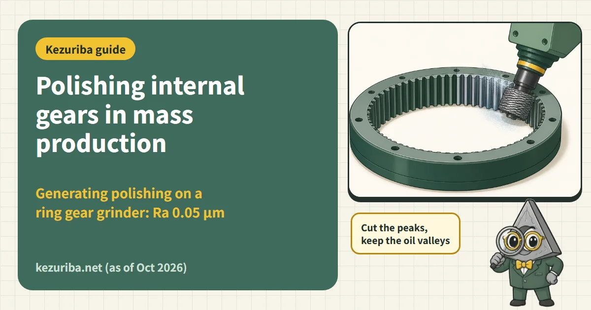
For external gears, "polish grinding", which mirror-finishes the tooth flanks after grinding, is already used in mass production. But the internal gear (ring gear) on the outside of a planetary gear set needs the tool to go inside the gear, so there was no way to polish it. Nidec Machine Tool and RWTH Aachen University in Germany tested a method that keeps the motion of an internal-gear generating grinding machine as is and swaps only the wheel for a polishing wheel, and confirmed that it can produce tooth flanks with a Ra 0.05µm mirror-like finish, with no grinding burn. The technique was announced in 2024 as "the world's first mass-production internal gear polishing method". This article walks through, with figures, why internal gears are hard to finish, why polishing makes gears last longer and run quieter, and how the conditions were determined in the paper (as of October 2026).
- 1Gear cutting
Cut the teeth by hobbing, shaping or skiving - 2Heat treat
Hardening makes it hard, but distorts the shape - 3Generating grinding
Corrects the distortion. Accuracy ISO grade 3–5, roughness Ra 0.35 µm or less - 4Polishing (this article)
Swap the wheel to remove only the peaks. Ra 0.1–0.05 µm
The flow of making an internal gear, and the step added here. Grinding and polishing values are from the paper[1].
Why Internal Gears Are Hard to Finish
Planetary gear mechanisms can achieve large reduction ratios while staying small and light, so they are widely used in hybrid and electric vehicle drive units, transmissions and robot joints. The outermost part, the internal gear, can cause noise and vibration even from slight distortion. In electric vehicles, which have no engine sound, that noise has become especially easy to hear[1][2].
Internal gears distort after hardening, so we would like to correct them by grinding, as with external gears. But the tool has to enter the narrow space inside the gear, so the large threaded wheels used for external gears do not fit. According to a 2009 Mitsubishi Heavy Industries (MHI) document, the industry had coped by improving cutting accuracy before hardening and had also tried honing with electroplated wheels, but high cost and low productivity meant none was a decisive answer[6][5].
So MHI (now carried on by Nidec Machine Tool) studied the machining theory with Prof. Hiroshi Gunbara of the National Institute of Technology, Matsue College, and in 2009 launched the world's first mass-production internal gear grinding machine, the ZI20A. Its distinguishing feature is a barrel-shaped threaded wheel, thick in the middle. The company says it raises sliding speed more than 4 times over honing and cuts tooling cost per part to about 1/6[5][6]. In 2024 the ZI25A, which can grind up to 250 mm outside diameter, was added as well[4].
Grinding alone keeps profile and helix deviations within ISO IT3 and can also correct pitch errors caused by heat treatment. However, flank roughness is limited to about Ra 0.35 µm, and going smoother needed a different approach[1]. In a comparison of wheels, a corundum wheel gave life and quality similar to a cBN wheel, with 1.5 times the productivity[7].
Why Polish the Tooth Flanks?
Magnified, a ground flank shows fine peaks and valleys. When gears mesh, a thin oil film forms between the flanks, but sharp peaks break through the oil film and hit the mating flank, causing friction and tiny scratches.
For external gears, the Swiss grinding machine maker Reishauer developed polish grinding in 2012. A single threaded wheel is divided into a hard grinding section (grit 80, average grain size 185 µm) and a resilient resin polishing section (grit 800, average 7 µm), and the process moves from grinding to polishing on the same machine with the same clamping. Roughness of about Ra 0.3 µm from continuous generating grinding is brought down, as a guide, to Ra 0.1 µm. Vibratory finishing (polishing in vibrating abrasive media) can also polish tooth flanks, but it needs a separate machine and transport[8].
What Smoothing Improves
- Longer life: In NASA tests, aerospace ground gears were superfinished by vibratory finishing (removing about 2.5 µm from the flank), and surface fatigue life rose about 4 times. The conditions were AISI 9310 material, 28 teeth and 1.71 GPa Hertz stress[9].
- Small cracks are slower to grow: The paper gives reducing the risk of surface microcracks growing as a main reason for polishing in trucks, buses and agricultural machinery[1].
- Less friction, higher efficiency: In drivetrains that run at high speed, such as in electric vehicles, improving efficiency and noise (NVH) is especially important[1][8]. A superfinishing vendor cites a 2007 study by GM and Ohio State University reporting that superfinished spur gears were about 17% more efficient than ground gears (this is the vendor's account, and it is more natural to read it as a difference in loss rather than in efficiency itself)[10].
The Nidec and RWTH Aachen Study
Mr. Fujimura of Nidec Machine Tool and Ms. Löhrer of the Laboratory for Machine Tools and Production Engineering (WZL) at RWTH Aachen University kept the motion of the ZI20A grinding machine as is and replaced only the wheel with a resin-bonded polishing wheel, and investigated the conditions for polishing an internal gear[1].
| Gears | Ring gear assumed for automotive use: module 1.25, 85 teeth, helix angle 20°, pressure angle 20°, profile shift coefficient 0.3, face width 30 mm, SCr415 (equivalent to 16MnCr5), 60 HRC |
|---|---|
| Grinding wheel | Resin-bonded corundum, grit 800, φ76 × 20 mm wide (few commercial products exist; chosen by comparing grit sizes and binders in preliminary tests) |
| Conditions varied | Wheel speed 1,500–11,945 rpm (sliding speed 3–24 m/s at a 30° cross-axis angle), radial infeed 0.02–0.25 mm, axial feed 0.02–0.04 mm per workpiece revolution. Nine test points |
| Method | Ground gears were used, and the wheel was dressed before each test; polishing was done in one pass |
| Pass criteria | Total profile and helix deviations within IT5 (measured on a gear measuring machine), roughness of Ra 0.1 µm and Rz 1.0 µm or less (stylus, profile direction, middle of the flank), and no grinding burn (nital etching) |
Test conditions[1].
Result 1: Infeed sets the roughness
At an infeed of 0.1 mm or more, roughness fell below the target of Ra 0.1 µm, and Ra 0.05 µm was reached at 0.15 mm. The measurement record of the gear finished at 0.1 mm was almost unchanged from before polishing, and it was also confirmed that polishing removed only the peaks of the roughness profile.[1].
Result 2: Spinning faster does not worsen roughness
Roughness does not change in a straight line with speed: it is finest at low speed, gets coarser as speed rises, then gets finer again above 8,000 rpm. Since productivity is set by speed, running at the top speed of 11,945 rpm gives about the same roughness as slow running in about 1/8 of the time.[1].
Result 3: Left and right flanks respond differently
Raising the axial feed from 0.02 to 0.04 mm lowered Ra on the left flank by 8% (0.12 to 0.11 µm) and raised it on the right flank by 33% (0.06 to 0.08 µm). The paper suggests that finishing the two flanks separately with different feeds is one option. Under every condition, no grinding burn appeared[1].
Conditions the paper recommendsRadial infeed 0.1–0.15 mm, wheel speed 11,945 rpm, axial feed 0.02–0.04 mm per revolution. This combination is expected to give a flank smoother than Ra 0.1 µm in the shortest time. But this is a first test: confirmation and repeat tests under the same conditions, tests with other wheels, and detailed evaluation by Rpk and Rvk are still to come, the paper says[1].
Roughness Scale and a Comparison of Internal Gear Finishing Methods
| Method | How it works | Roughness / accuracy (examples) | Strengths | Notes |
|---|---|---|---|---|
| Generating grinding(barrel-shaped threaded wheel) | Wheel tilted 20–35° and rotated in sync with the gear | Within IT3, Ra 0.35 µm or less | Corrects heat-treatment distortion (pitch error); fast | Grinding burn must be controlled |
| Internal gear honing | Meshes with a gear-shaped wheel and cuts slowly at 0.3–5 m/s | Ra 0.23 µm in a test example | Almost no heat; leaves a large compressive residual stress (-1,000 to -1,600 MPa) at the surface | Removes little stock |
| SkiveFinishing(Liebherr) | Finishes with an electroplated cBN tool using skiving motion | ISO grade 5, under Ra 0.4 µm (manufacturer's claim) | No dressing needed; flank modifications can be applied directly | Figures are the manufacturer's early results |
| Polishing (this article) | Polishes with a resin wheel, keeping the generating grinder's motion | Holds IT5 or better, Ra 0.05 µm | Same principle as the grinder, no grinding burn, 29 s | Still an initial test. Only one type of wheel |
| Vibratory finishing / superfinishing | Smooths the surface with vibrating abrasive media (plus a chemical solution) | Under Ra 0.1 µm (vendor material) | Smooth, non-directional surface; a test example with about 4 times the life | Needs a separate machine and transport; processes in batches |
Sources: paper[1], ZI25A document[4], honing paper[11], SkiveFinishing abstract[12], REM[10], NASA[9].
What it means on the shop floor
- If you already have an internal gear grinding machine, just swap the wheel and you should be able to polish with the same setup (the paper polished ground parts in one pass)
- Rule of thumb: infeed of 0.1–0.15 mm. Too deep and accuracy breaks down
- Measure roughness on the left and right flanks separately. Feed affects them differently
- Look at peak height (Rpk) and valley depth (Rvk), not only Ra
- Even after polishing, keep the grinding burn inspection (nital etching)
- Ra 0.1 µm-class specifications, as for external gears, are becoming possible for planetary ring gears
- The aim is longer life (microcracks, surface fatigue) and better efficiency and noise
- If a drawing specifies only roughness, you cannot tell a surface with the peaks removed from one that is merely fine. Agree on Rpk and Rvk as well if needed
- This technology is still at the announcement stage, so confirm production track record and cost with the machining shop
FAQ
- How is polishing different from grinding?
- Both cut with a wheel, but grinding uses coarse grit and a hard binder to create the shape, while polishing uses fine grit (here grit 800) and a resilient resin binder to remove only the surface peaks. Polishing does not change the shape[8][1].
- How much material is removed?
- A radial infeed of 0.1–0.15 mm set on the machine is recommended. For gears finished at 0.1 mm infeed, the increase in dimension between balls was 0.004 mm, within the scatter of grinding[1].
- Is a shinier, mirror-like surface always better?
- Not necessarily. In polish grinding of external gears, leaving the valleys that hold oil is said to be important. Even at the same Ra, a surface with high peaks and shallow valleys performs very differently from one with low peaks and deep valleys[8].
- Which is better, compared with honing?
- Honing's strengths are that it generates almost no heat and leaves a large compressive residual stress at the surface[11]. Generating grinding and polishing are strong in the ability and speed to correct heat-treatment distortion and in fine roughness. Choose by gear size, amount of distortion and required roughness.
- What kinds of internal gears can it be used for?
- The paper's tests used an automotive ring gear with module 1.25 and 85 teeth. The ZI25A grinding machine handles module 1–3 and outside diameters up to 250 mm[1][4].
For gear basics and accuracy grades, see Gear study; for machining methods such as grinding and honing, see Gear machining methods, and for how changing the flank shape from tooth to tooth cancels noise, see the MicroForm article.
Sources
- N. Fujimura (Nidec Machine Tool) and P. de Oliveira Löhrer (WZL, RWTH Aachen University), "Application-oriented research on internal generating polishing" (attached to Nidec's announcement of 2024-02-09, PDF)
- Nidec, "Development of Nidec Machine Tool's World-First Mass-Production Internal Gear Polishing Method" (2024-02-09)
- MONOist, "Machining method developed to finish internal gears for planetary gear mechanisms with high precision" (2024-03-08)
- Nidec Machine Tool, "ZI25A mass-production internal gear grinding machine added to the lineup and put on sale" (2024-10-16)
- Mitsubishi Heavy Industries, "Finishing internal gears quickly, accurately and at low cost to reduce gear noise: development of the ZI20A internal gear grinding machine" (January 2009)
- Yanase et al., "Development of the World's First Mass-Production Internal Gear Grinding Machine ZI20A", Mitsubishi Heavy Industries Technical Review Vol. 46 No. 3 (2009)
- "Practical analysis of productivity of grinding tools in the process of internal generating gear grinding", Procedia CIRP Vol. 118 (2023) pp. 608–613
- W. Graf (Reishauer), "Polish Grinding of Gears", Gear Technology (November 2023, PDF)
- NASA Technical Reports Server, "Gear Durability Shown To Be Improved by Superfinishing" (Research and Technology 1999)
- REM Surface Engineering, "Surface finish improvement for gear and bearing system gains"
- "Aspects of the Internal Gear Honing Process" (ResearchGate)
- Motion + Power Manufacturers Alliance, "SkiveFinishing® – Introduction of a new hard finishing process for internal gears" (webinar abstract, 2026)
More articles
 Gears
GearsTwo New Fixes for Gear Skiving's Weak Points: Nachi-Fujikoshi's Air Skiving and Liebherr's SkiveFinishing, Illustrated
 Industry
How a Metalworking Company Can Enter the U.S. Defense Industry: Entry Points, SAM.gov and JCP, ITAR, CMMC, Specialty Metals, Hurdles
 Industry