Measuring by comparison
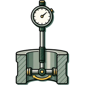
Dial bore gaugeBore gauge / Cylinder gauge
Also called: bore gauge, inside diameter gauge
≡Standards, measuring range and accuracy
- Standard
- JIS B 7515:1982 Cylinder gauges[1][2]
- Measuring range
- General Min 6 mm – max 450 mm (TECLOCK lineup)
- byMaker
- Mitutoyo CG-AX (511-701–706) 18–35 mm to 250–400 mm
- Niigata Seiki WCDI-35 18–35 mm (7 interchangeable rods)
- Resolution / graduation
- General Determined by the graduation of the indicator (dial indicator) used (e.g. 0.01 mm, 0.001 mm)
- Accuracy (instrument error / maximum permissible error)
- Approach Measured by comparison with a master (ring gauge, micrometer, etc.). JIS B 7515 tests indication accuracy, repeatability, the difference when the contact point is rotated 90° at a time, the effect of the guide plate, measuring force, and so on
- byMaker
- Mitutoyo CG-AX Repeatability 0.5 µm, measuring force 4–6 N or less
▦Types
◎Part names and functions
| # | Name | English | Function |
|---|---|---|---|
| 1 | Contact point | Contact point | The side that touches the inside of the hole and moves.[3][2][6] |
| 2 | Interchangeable rod (anvil) / rod adjusting screw | Exchange rod (anvil), rod adjusting screw | The fixed side, swapped to suit the size being measured.[3][2][6] |
| 3 | Guide plate | Guide | Guides the contact point and the interchangeable rod to the diameter position of the hole (self-centering).[3][2][6] |
| 4 | Outer tube / grip | Outer tube, grip | The part you hold in your hand.[3][6] |
| 5 | Indicator (dial indicator) / mounting screw (clamp screw) | Indicator, clamp screw | Reads the movement of the contact point.[3][2][6] |
| 6 | Push rod / extension / cam mechanism (internal) | Push rod, extension, cam | Converts the contact point displacement 1:1 through a right-angle cam and passes it to the indicator.[2] |
◷How to read the scale
- The reading is the difference from the reference (the master size set to 0). Add or subtract the difference to or from the master size to get the bore diameter[3][2][5]
- The 'turning point' of the pointer when you rock the gauge is the diameter position. In a section containing the hole axis, the indicator points to its maximum when the diameter is at its minimum[3][7]
Rock the gauge in a plane that contains the hole axis. The pointer turns back when the contact point is perpendicular to the hole axis (when the span is at its shortest), and the indicator reading is at its maximum there. Read the value at that point and add it to or subtract it from the master (reference) dimension.
✋Usage steps
- Assembly: loosen the mounting screw, insert the indicator, push it in until the long hand turns 1/10 revolution or more, and fix it[3]
- Selecting the rod: choose the rod that suits the size to be measured and adjust the screw-in so that the distance from the contact point tip to the rod tip is about 0.5 mm longer than the target size, then lock it[3]
- Cleaning and clamping: wipe the contact point and anvil with a dry cloth and tighten the clamp screw firmly[6]
- Zeroing: insert into a ring gauge (setting ring) or micrometer, rock it, and set zero at the point where the indicator reads maximum. Turn the bezel to bring the long hand to 0The diameter in a section perpendicular to the axis (maximum) is found automatically by the guide plate. The diameter in a section containing the axis (minimum) is found by rocking by hand. When setting with an outside micrometer, use the micrometer upright (Mitutoyo)[3][7][8][6]
- Insertion: tilt the handle and put the guide plate side in first, then the anvil[6]
- Measuring: rock it while watching the scale and read at the point where the indicator shows its maximum (the diameter position). The reading is the difference from the reference ring[3][7]
Printed from Kezuriba (kezuriba.net/en/gauges/cylinder-gauge/)
!Common measurement mistakes and countermeasures
Mixing up how maximum and minimum are described
WhySources word it differently: 'maximum of the indicator' (Niigata Seiki, Mitutoyo English), 'position where the contact point is pushed in the most' (Mitutoyo Japanese), 'minimum indication' (the JIS excerpt in TECLOCK). All refer to the turning point where the diameter is smallest
CountermeasureRemember: 'the point where the pointer turns back = the true diameter'[3][7][8][2]
Reading without rocking
WhyYou read a longer dimension from a tilted position
CountermeasureAlways rock it and find the turning point[3][5]
Temperature change and condensation (small-bore type)
WhyMoving between indoors and outdoors causes condensation, which corrodes the contact point
CountermeasureAvoid large temperature changes[6]
✓Care, storage, inspection and calibration
Care and storage
- After use, check for damage and clean. If dirt may have got inside, disassemble and clean it, and after drying apply a thin coat of micrometer oil (Mitutoyo)[6]
- Use the supplied accessories such as interchangeable rods and do not mix them with others. After use, apply rust prevention and put it in the case[3]
- Do not drop, disassemble or modify (manufacturer's manual)[3]
Inspection and calibration
- Set zero with a ring gauge, cylindrical master, micrometer, gauge block attachment, bore gauge checker, etc.[6][7][5][2]
- JIS B 7515 tests include: pushing in 0.1 mm at a time against a reference indicator and plotting an error curve; rocking 3 round trips in a ring gauge and reading the minimum indication, repeated 3 times to find the difference[2]
The rocking motion and the pointer's turning point suit a diagram (Niigata Seiki manual, Figs. 1–3: diameter a, in a section perpendicular to the axis, is the maximum, found automatically by the guide plate; diameter b, in a section containing the axis, is the minimum, found by rocking by hand).
⇄Related instruments
📚Sources
Content without a mark is what agreed across two or more sources from different publishers. Procedures and cautions are summarized in Kezuriba's own words based on the sources, and the diagrams were drawn by Kezuriba. Accuracy values are manufacturers' published figures, not values from JIS tables.
- Japanese Standards Association (JSA), "JIS B 7515:1982 Cylinder gauges (bibliographic record)"
- Teclock, "General Catalog 8: Cylinder Gauges and Micro Hole Tests (includes excerpts of JIS B 7515)"
- Niigata Seiki, "Standard Cylinder Gauge WCDI-35 Instruction Manual"
- Mitutoyo, "Cylinder Gauge CG-AX 511-701 Specifications"
- Mitutoyo, "Mitutoyo Product Fundamentals (Bulletin No. 2180, Mitutoyo America)"
- Mitutoyo, "Check Points for Measuring Instruments (Catalog No. E12024)"
- Mitutoyo, "How to Use Bore Measuring Instruments, Basics"
- Mitutoyo, "Quick Guide to Precision Measuring Instruments (Catalog No. E11003(7), as of August 2024)"