LATHELathe
A lathe is a machine tool that spins the workpiece and presses a cutting tool against it to cut round shapes. One machine can do OD turning, facing, boring, grooving, threading, and taper turning. This page covers lathe types and parts, how to read specs, insert designations, cutting conditions, and setup, checked against public materials from tooling and machine tool makers and training materials from the Ministry of Health, Labour and Welfare (MHLW).Write G-code in the simulator below to cut in 3D; change the conditions and the spindle speed, surface finish, power, and deflection update on the spot.
The work spins,
the tool just
moves!

▦Types of Lathes
Manual (engine) latheManual (engine) lathe
A lathe with a headstock, tailstock, and carriage (with a tool post on top) mounted on a bed. The operator moves the tool with handwheels and feed levers to do OD turning, boring, drilling, taper turning, threading, and knurling. Fit a center or drill chuck in the tailstock and you can also do work between centers, drilling, tapping, and reaming.[1][2]
StrengthsOne-offs, prototypes, repairs. Skill building: MHLW’s manual says that even where CNC lathes dominate, the skills of deciding machining steps, tools, and conditions, and the skills of measurement, are learned by actually using a manual lathe, so off-the-job training on manual machines is needed.[3]
CNC latheCNC lathe
A lathe whose NC controller reads a part program, written under fixed conventions to describe tool motion and cutting conditions, and machines automatically. Most have a turret tool post. With numerical control and automatic tool changing, it can cut curved and complex shapes.[4][5]
StrengthsVolume and repeat production. MHLW’s manual lists five advantages over a manual lathe: it can machine without skilled operators and prevents mistakes in method and conditions; accuracy varies little, so quality and productivity go together; one person can run several machines; and programs are easy to create with conversational programming or CAD/CAM.[4]
Turning centerTurning center
A CNC lathe with enhanced functions and many tools, plus a rotary-tool (milling) spindle so it can also mill and drill. Example: the Okuma LBⅢ M spec can fit turning or rotary tools in every station of its 12-station composite turret, and the MY spec consolidates operations with a Y axis.[6][7]
Multitasking machine (lathe type)Multi-tasking machine (mill-turn)
A turning center with a rotary-tool spindle that can swivel (index) while machining. Besides turning, one machine handles milling, angled holes, grooves, and even hobbing. Example: the Okuma MULTUS BⅡ has a B-axis swiveling tool spindle and an ATC (HSK-A63, 20–80 tools).[6][5][8]
StrengthsProcess consolidation (fewer setup changes). Okuma presents specs that handle gear machining and even skiving (internal splines) on a multitasking machine.[8]
Sliding-headstock (Swiss-type) CNC automatic latheSliding-headstock (Swiss-type) automatic lathe
The headstock gripping the bar itself moves in the axial direction (Z), and the guide bush supports the bar right next to the cutting point while the tool just in front of the guide bush cuts. This is why spec tables list “max. headstock travel” (for example 205 mm on the Star SR-20JⅡ). Some models can switch to operation without the guide bush (non-guide-bush mode; 50 mm travel on the same machine).[9][10][11]
StrengthsHigh-accuracy, high-speed machining of thin, long small parts. Citizen describes Cincom as sliding-headstock machines built on the small-diameter, high-accuracy machining know-how developed with watch parts (its lineup includes models with max. machining diameters of ø12, ø16, ø20, and so on). Star’s lineup lists models with max. machining diameters of 10–51 mm.[9][12][10]
Fixed-headstock CNC automatic latheFixed-headstock CNC automatic lathe
An automatic lathe whose headstock stays put while the tool post side, such as a turret, moves (there are bar machines fed from a bar feeder and chucker machines that grip one blank at a time). Citizen’s Miyano focuses on rigid models capable of heavy cutting, with models of 42–80 mm max. bar capacity.[9][13]
Vertical turning lathe (VTL)Vertical turning lathe
A lathe with a vertical spindle and the chuck facing up. The workpiece sits against the chuck’s reference surface under its own weight, which reduces distortion from clamping force and lets it cut everything from thin parts to large-diameter, heavy ones stably. You also don’t need to support an odd-shaped workpiece by hand while chucking it. Example: the Okuma V100R has a max. turning diameter of 1,000 mm and max. turning length (height) of 890 mm.[14]
▶CNC Lathe Simulator: Write G-code and Cut in 3D
Reads FANUC-style lathe G-code (G00–G03, G50, G96/G97, G99, and G32/G92 threading). The stock is a ø40 round bar and the origin is at the center of the end face. Switch to “Section and toolpath” to see the tool’s path and a DRO. Press ▶ Run to cut: dark areas are still stock and bright areas are cut surface.
┅ Rapid G00━ Cutting feed━ Threading
Five exercises that grade whether you cut to the drawing (facing, stepped, taper, arc, thread) are in NC Lathe Programming Basics.
The simulator is for seeing how things work. Nose radius and tool interference are simplified. On a real machine, check the machine builder’s operation manual and parameters.
◎Visualize Turning Conditions
Change the work material, diameter, cutting speed, feed, depth of cut, corner radius, and tool, and the spindle speed (G50 limit), theoretical surface finish, chip thickness, main cutting force and power, tool deflection, and tool life all change at once. Raise any one of them and watch what else it affects.
⚙Parts of a Lathe
- Carriage (saddle, cross slide, tool post, apron)The part that gives the tool feed and positioning. It moves along the bed ways in the direction of the spindle centerline (Z), and the cross slide on top moves at right angles (X). The carriage is made up of the saddle, cross slide, swivel base, upper slide (compound rest), tool post, and apron.[2][1]
- Compound rest (upper slide)The tool post can be tilted and locked; with the carriage held still, you feed with the compound rest handle to cut a taper. Drawings specify a taper as “1:A,” so the tool post angle is found from the slope, as in tanθ = 0.5/A (5.71° for 1:5).One source / reference[1]
- TailstockSupports one end of a long workpiece with the center at the tip of the tailstock spindle. It also guides drills and reamers for drilling and reaming. There are dead centers (fixed centers) and live centers.[2][1]If the tailstock support force is too strong or too weak, the roundness of the workpiece changes (an experiment at Nihon University; the thrust force acts differently at the chuck side and the tailstock side).
- Feed and threading mechanism (lead screw, feed rod)A combination of lead screw, feed rod, and gears that takes the spindle’s rotation and gives accurate feed to the carriage and cross slide. In threading, the lead screw feeds the carriage.One source / reference[2]
- Types of Chucks3-jaw scroll (self-centering) chuck: the three jaws move together, so round and hex stock loads and unloads quickly. 4-jaw (independent) chuck: each jaw moves separately, so it can hold irregular and off-center workpieces and allows centering (truing), but the center of gravity is off the center of rotation, so it can’t be used at high speed. Hydraulic and pneumatic power chucks: suited to CNC lathes and automation, with large gripping force. Soft jaws: unhardened jaws machined to fit the workpiece shape, holding it without marring the finished surface.[5][1][3]
- Tool Post Types: Gang Tool and TurretA gang tool post lines tools up in a row and selects a tool by moving the tool post (common on small sliding-headstock automatic lathes; example: the Star SR-20JⅡ has six □12 mm tools). A turret tool post arranges tools around its circumference and selects one by indexing (examples: the Okuma LBⅢ has a 12-sided V12 turret; Citizen Miyano has 8–12 stations). Kyocera shows gang-type, opposed gang-type, and turret-type layouts in diagrams as examples of tooling for small CNC automatic lathes.[15][7][13][10]
≡How to Read the Specs
| Item | Meaning and examples |
|---|---|
| Max. turning diameter, swing | The largest diameter of workpiece that can be cut. CNC lathe spec tables usually give it as “max. turning diameter” (examples: Okuma LB35Ⅲ ø460 mm, LB45Ⅲ ø660 mm, MULTUS B300Ⅱ ø630 mm, V100R ø1,000 mm).[7][8][14]We could not confirm the definitions of “swing over bed” and “swing over carriage” used for manual lathes, because the primary source (JIS B 0105) was not available to read. An encyclopedia (as a lead) explains swing over bed as the largest diameter that can rotate without hitting the bed, and swing over carriage as the largest diameter that can rotate without hitting the carriage. |
| Max. turning length, distance between centers | The maximum length that can be cut. Spec tables give it as “max. turning length” (example: LB35Ⅲ 850, 1,500, 2,000 mm) or “distance between centers” (between the spindle and tailstock centers; example: MULTUS B300Ⅱ 900 mm). Vertical lathes give “max. turning length (height)” (V100R 890 mm).[7][8][14] |
| Spindle nose (JIS A2-6, etc.) | The shape and size of the spindle tip where the chuck mounts. Domestic spec tables write it as A2-6 or A2-8 (examples: MULTUS B250Ⅱ and B300Ⅱ are A2-6; B400Ⅱ and V40R are A2-8). Chuck makers put A2-5, A2-6, A2-8, A2-11, and A2-15, mounting shapes conforming to JIS B 6109-1 and -2 (2005), in their model codes (Kitagawa: A5, A6, A8…; Howa: A5, A6, A8). The larger the number, the larger the spindle nose.[8][14][16][17]"The larger the number, the larger the nose" is taken from Kitagawa's model sequence (A2-5 → A2-15) and how it matches chuck sizes |
| Spindle bore, max. bar capacity | The thickness of bar that can pass through the spindle. For machines that feed bar for continuous machining, “max. bar capacity” is the heart of the spec (examples: Citizen Miyano BNA42 is 42 mm, BNE65ATC is 65 mm). Some give the spindle’s inner diameter as “spindle bearing bore” (MULTUS BⅡ ø100, ø120 mm), or as the spindle’s outer and inner diameters listed alongside the spindle nose type (V40R: ø120, ø77 mm).[13][8][14] |
| Chuck size | Given in inches (examples: LB35Ⅲ 12 in, LB45Ⅲ 15 in, V100R 36 and 40 in)[7][14] |
| Spindle speed, power, torque | The maximum speed (example: LB35Ⅲ 3,200 min⁻¹) and the main motor output, written with two ratings as in “30/22 kW (30 min/continuous).” The first is the short-time rating and the second the continuous rating. Machines with gear changing can produce large torque in the low speed range (LB35Ⅲ max. torque 1,308/959 N·m).[7][8] |
| Number of tools (turret stations, ATC capacity) | Turrets are given by number of sides (V12 = 12 stations). Multitasking machines list the ATC capacity (MULTUS BⅡ has 20 tools, with 40, 60, and 80 optional) and tool shank (HSK-A63). Gang-tool automatic lathes list the number of tools (SR-20JⅡ: six □12 mm) and the number of rotary tools.[7][8][10] |
◐What a Lathe Can Do
OD turning, profile turning
The cutting edge moves axially along the workpiece to cut the outer surface. In profile turning, it also moves in the depth-of-cut direction to produce slopes and curved surfaces.[5][6]
Facing
The cutting edge crosses the end face in the radial direction. You can cut toward the center, or back outward from the center.[5][6]
Boring (ID turning)
A boring bar cuts the inside of an existing hole to finish its diameter and surface.[5][6][1]
Grooving (OD, ID, face)
The cutting edge is fed at right angles into the workpiece to form a groove. Narrow grooves are plunged in several passes; wide grooves combine plunging with cross feed (Mitsubishi Materials: planning the plunge order keeps chips from stretching out and gives good wall accuracy).[5][18]
Parting off
The cutting edge is fed to the center to separate the workpiece. Mitsubishi Materials’ cautions: reduce the feed to 50% near the center and stop the feed just before reaching the center (the workpiece drops under its own weight). With constant surface speed, rotation speeds up as you approach the center, so limit the spindle speed to about 80% of the machine’s maximum, and lowering the speed just before the cut-off prevents the workpiece from flying out.[5][18][6]
Threading (OD, ID)
A threading tool is fed axially to form the thread. Normally the depth is cut in several passes. The infeed methods are radial (straight), flank, modified flank, and alternating flank. Radial makes conditions easy to change but chip control is difficult and it tends to chatter; flank types send chips in one direction, making them easier to handle.[5][19][20]
Taper turning
On a manual lathe, tilt the compound rest and feed by hand. On a CNC lathe, move X and Z simultaneously.[1][3]
Radii (arcs) and chamfers
A CNC lathe cuts arcs with circular interpolation. Because the tool has a nose radius, tapers and arcs come out off size unless you use tool nose radius compensation.[4]
Knurling
A knurling wheel is pressed against the surface to form a non-slip pattern. Pattern types are straight (parallel to the axis), right-hand, left-hand, diamond (raised or recessed), and cross (IS 3403, in the DIN 82 family, lists RAA, RBL, RBR, RGE, RGV, RKE, and RKV). Pitches are 0.5, 0.6, 0.8, 1.0, 1.2, and 1.6 mm, with a 90° peak angle. Pressing raises the material, so make the diameter before knurling smaller than the finished OD according to the pitch.[21][3]
◆Insert Designation Codes
CNMG 120408 (C = 80° rhombic, N = 0° clearance angle, M = M grade, G = cylindrical hole with double-sided breaker, 12 = cutting edge length in the 12 mm range, 04 = thickness 4.76 mm, 08 = nose radius 0.8 mm)
| Position | Item | Symbol and meaning |
|---|---|---|
| 1 | ShapeC | CRhombic 80°DRhombic 55°VRhombic 35°SSquare 90°TEquilateral triangle 60°WTrigon (equilateral, unequal-angle hexagon) 80°RRound[25][5][26]Mitsubishi Materials’ e-learning: the 80° rhombic can cut both OD and face and is the most used on CNC lathes. The 55° and 35° suit profile turning but have weak edges. The square has a strong edge and four corners per side (eight in total if negative) but can’t cut right angles. The round has the strongest edge and a good finish, but its chips are wide and don’t break easily. ISCAR also gives A, B, K (parallelogram), H (hexagon), and O (octagon) as examples. |
| 2 | Clearance angleN | N0° (negative insert)P11°B5°C7°A3°D15°[25][5][26]B and C are from Sumitomo only, A and D from ISCAR only. Inserts with 0° clearance are called negative, others positive (Mitsubishi Materials). Negative inserts can have chipbreakers on both faces; positive ones only on one (Mitsubishi Materials) |
| 3 | Tolerance (grade)M | A combination of three tolerances: corner height, inscribed circle, and thickness. Grades A–J are ground for accuracy (collectively called G grade); grades K–U are ground only on the top and bottom faces (collectively called M grade). Turning mainly uses G grade (sometimes J grade) or M grade. Example: for Sumitomo, E and G grades have an inscribed circle and thickness of ±0.025 mm, and M grade has an inscribed circle of ±0.05 to ±0.15 mm (varies with size).[5][25][23] |
| 4 | Hole and breaker (groove)G | NNo hole, no breakerACylindrical hole, no breakerMCylindrical hole, single-sided breakerGCylindrical hole, double-sided breakerWCylindrical hole + single-sided chamfer (40–60°), no breakerTCylindrical hole + single-sided chamfer, single-sided breakerXSpecial[25][26]The other letters are from Sumitomo's table only |
| 5 | Size (metric: cutting edge length, inch: inscribed circle)12 | The metric system writes the cutting edge length (its integer part) as two digits, so the symbol changes with shape even for the same inscribed circle. The inch system writes the inscribed circle as a number in 1/8 inch units (3 = 3/8 in = 9.525 mm, 4 = 12.70 mm). Example: in Sumitomo’s table, 12 for shape C means a cutting edge length of 12.9 mm and an inscribed circle of 12.70 mm.[5][25]ISCAR writes the “12” of CNMG 120404 as “size 12.7 mm,” which is the inscribed circle value (it does not say cutting edge length). |
| 6 | Thickness04 | 011.59 mm022.38 mm033.18 mmT33.97 mm044.76 mm066.35 mm[25][26]04 = 4.76 mm agrees between ISCAR and Sumitomo |
| 7 | Corner radius (nose radius)08 | 121.2 mm161.6 mm202.0 mm242.4 mm00Sharp010.1 mm020.2 mm040.4 mm080.8 mm[25][26]Mitsubishi Materials’ e-learning explains it as 0.4 mm steps from 0.4 mm (0.8 mm steps from 4.0 mm) |
| 8 | Edge preparation (honing)(E) | There are round honing, chamfer honing, and others, and each manufacturer sets the dimensions by grade and size. It is often omitted from the designation.[5][27]We could not confirm in the body of the primary source what the symbol letters (E, F, S, T, etc.) mean. |
| 9 | Hand(N) | The direction it can cut (right or left). Neutral inserts, which can be used either way, are often omitted.[5] |
| 10 | Chipbreaker-MA etc. | Each manufacturer defines its own breaker shapes, so the symbols are also manufacturer-specific (optional). Example: in ISCAR’s CNMG 120404-F3P, F = finishing, 3 = medium load, P = for steel.[5][26] |
Cutting Edge Angles
- Rake angleGreatly affects cutting force, chip evacuation, cutting heat, and tool life. Making it larger toward positive (+) improves cutting action (lowers cutting force) but weakens the edge. When edge strength is needed, as with mill scale or interrupted cuts, use a smaller (or negative) angle. Mitsubishi Materials: each 1° more positive lowers cutting power by about 1%.[28][15][26]“1% per 1°” is the same size as the rake angle correction (1 − γ/100) that ISCAR and Sandvik apply to specific cutting force.
- End cutting edge angleThe angle that keeps the end cutting edge from interfering with the cut surface, usually 5–15°. A smaller angle makes the edge stronger but raises passive force and invites chatter. Use smaller for roughing and larger for finishing.One source / reference[30]
- Inclination angleThe angle that keeps the impact at the start of a heavy cut from landing on the tip of the cutting edge. 3–5° is recommended for turning. Negative sends chips toward the workpiece, positive sends them the opposite way. Negative makes the edge stronger but raises passive force and invites chatter.One source / reference[30]
- Honing, landEdge preparation that keeps the cutting edge strong. More honing makes chipping less likely, but flank wear progresses more easily and cutting force rises, inviting chatter. Mitsubishi Materials says a honing width of about 1/2 of the feed is optimal. Carbide, coated, and cermet inserts come with round honing as standard.One source / reference[27]
Overhang
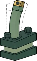
- Boring bar overhang (L/D)The larger the ratio L/D of overhang L to bar diameter D, the more it chatters. Mitsubishi Materials: with a steel shank, chatter becomes likely once L/D exceeds 4–5, which limits depth of cut and feed. Heavy-metal or carbide shanks raise rigidity and allow cutting at a larger L/D.[5][15]
- Tool center heightMatch the height of the tool tip to the spindle center. On a manual lathe, you either transfer the spindle center with a surface gauge scriber and set the tool height to it, or compare the height of a live center tip with the cutting edge, and adjust with as few shims as possible.One source / reference[1]
≈How to Set Cutting Conditions
- Cutting speedCutting speed has the biggest effect on tool life. Mitsubishi Materials: raise the speed 20% and life halves; raise it 50% and life drops to 1/5. Low speeds (20–40 m/min) also chatter easily and shorten life.One source / reference[34]Equivalent to m ≈ 0.25 in Taylor's equation (ISCAR)
- FeedFeed is closely tied to surface roughness, and is mostly decided by the required roughness. Theoretical roughness is h = f²/(8r). Making the feed too small increases flank wear and shortens tool life drastically. A larger feed raises cutting temperature, but its effect on life is smaller than cutting speed.[34][32][15][20]
- Depth of cutDepth of cut is set by stock allowance, part shape, machine power and rigidity, and tool rigidity. Tool life changes little with depth of cut. A very small depth of cut rubs the surface and cuts into the work-hardened layer, which shortens tool life. For mill scale and cast skin, use as large a depth of cut as the machine power allows so the edge gets under the hard surface layerOne source / reference[34]
Example conditions (S45C etc., MHLW training material)
| Tool / operation | Cutting speed m/min | Depth of cut mm (radial) | Depth of cut mm | Feed mm/rev |
|---|---|---|---|---|
| HSS[1] | 20–30 | — | — | — |
| Carbide (semi-finishing to roughing, nose R 0.2–0.4)[1] | 80–130 | 0.5–2 | — | 0.15–0.30 |
| Cermet (finishing, nose R 0.2–0.4)[1] | 160–200 | 0.1–0.5 | — | 0.05–0.15 |
| CNC lathe roughing (carbide, nose R 0.8)[4] | 100–120 | — | 2.0–3.0 | 0.2–0.3 |
| CNC lathe finishing (cermet, nose R 0.4)[4] | 160–180 | — | 0.1–0.2 | 0.05–0.1 |
Surface finish vs. feed guide (corner R 0.2–0.4)
| Ra (µm) | Feed mm/rev |
|---|---|
| 25 | 0.25–0.30 |
| 6.3 | 0.10–0.15 |
| 1.6 | 0.05–0.08 |
“Recommended feed rate” from the MHLW manual lathe manual (for a nose radius of 0.2–0.4 mm). It is on the safe side of the theoretical roughness formula (theoretical Rz ≈ 7 µm at r = 0.4 and f = 0.15)[1]
- Wiper insertsA wiper insert has a finishing edge (the wiper) between the corner radius and the straight cutting edge. It keeps surface finish even at a higher feed, so it can shorten machining time or combine roughing and finishing in one operation, and the thicker chips break more easily. Mitsubishi states that surface finish is maintained even with the feed doubled. On radii and on tapers of 5° or more, the roughness is about the same as with a standard insert. DNMX and TNMX need a holder with a 93° end cutting edge angle, and the shape of the inside corner changes (gouging or stock left)[35][15]
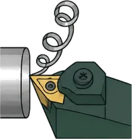
- Chip controlTo break chips shorter, raising the feed, reducing the side cutting edge angle (increasing the approach angle), or reducing the corner radius all work by making the chip thicker. Chip forms are classified from A (irregular, tangled) to E (fine fragments); the short helical to one-turn-or-less C and D forms are good. A and B forms cause wrap-around, poor chip removal, and safety problems; the E form causes scattering, chatter, and heat[20][23][30][31][15]
Compensation when the corner R is changed
- A table and formula give the tool offset change ΔX and ΔZ when you change the insert corner R, based on the holder shape (insert point angle and approach angle). Example: for PCLN (80°, 95°), changing R0.8 to R0.4 gives ΔX = ΔZ = 0.100 × (0.8 − 0.4) = 0.04 mmOne source / reference[15]
For tool nose radius compensation (G41/G42) and imaginary tool tip numbers, see NC Lathe Programming Basics.
⚙Setup
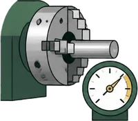
- Centering (truing)Aligning the spindle's center of rotation with the center axis of the workpiece. Put protective plates on the jaws if needed, tighten as evenly as possible while watching the runout, then touch a dial indicator to the work and turn the spindle slowly to read the runout. With a 4-jaw chuck, the usual way is to repeatedly tighten and loosen the jaws until it is alignedOne source / reference[3][1]In National Skills Competition tasks, centering is done about 50 times, and top competitors take 2–3 minutes each. Centering targets: roughing 0.1–0.3 mm, semi-finishing 0.01–0.03 mm, finishing 0–0.002 mm (competition level)
- Holding with a 3-jaw chuckWhile turning the workpiece lightly, tighten the 3 jaws evenly in turn. In the manual lathe task (ø60), the workpiece sticks out about 65–80 mm from the chuck and is clamped firmlyOne source / reference[1]
- Forming soft jawsFor OD gripping, clamp a forming plug; for ID gripping, clamp a forming ring. While it is clamped, cut the jaws to the workpiece diameter. Size the plug so that it is gripped near the middle of the jaw stroke, and clamp it pressed against the chuck face so it does not tilt. The hydraulic (gripping) pressure during forming must be the same as during actual machining. After forming, check slip and accuracy with a trial cut[16][17][4]Kitagawa says “the same as for machining or slightly higher”; Howa says “the same.” Kitagawa sets the gripping diameter equal to the workpiece diameter (about H7 for OD gripping) and the surface finish at 6.3s or finer, and says that ID gripping should be used at 1/2 or less of the maximum permissible input for OD gripping. Howa asks that OD gripping not be done in the inner 1/4 of the jaw stroke. The MHLW CNC lathe manual says that forming separate soft jaws for the first and second operations and starting machining without removing them keeps accuracy better
- Using the tailstockSupport a long workpiece by drilling a center hole in its end and pressing a live center against it. Too much or too little pressure affects roundnessOne source / reference[3][36]No numerical guideline for the L/D at which a tailstock or steady rest should be used was found in public primary sources
- Leaving stock (rough → semi-finish → finish)Leave 1 mm on diameter (0.5 mm per side) from the finish size after roughing, and 0.2 mm on diameter (0.1 mm per side) after semi-finishing. The material expands from heat during machining, so allow for that when deciding the target sizeOne source / reference[3]
- Target sizeWhen there is a dimensional tolerance, aim for the middle of the tolerance (example: for ø40 −0.05/−0.10, aim for 39.925)One source / reference[1]
- Setting the depth of cutWhen accuracy matters, set the depth of cut by the dial indicator placed behind the tool post or turret, not by the machine's own graduationsOne source / reference[3]
!Common mistakes
- Not setting a spindle speed limit with G96In parting off and facing, the speed rises as the tool nears the center, which can make the cut unstable near the maximum speed or throw the workpiece out. Mitsubishi cautions to limit speed to about 80% of the maximumOne source / reference[18]
- Forming soft jaws at a different gripping pressure than for machiningUse the same forming pressure as for machining (Kitagawa: the same or slightly higher). If it differs, gripping accuracy is lost[16][17]“If it differs, gripping accuracy is lost” is our wording for why both makers ask for matching pressure; it is not a direct quote
- High speed with heavy top jaws (large soft jaws)While rotating, centrifugal force acts on the jaws and reduces the gripping force in OD gripping. The loss is proportional to the square of the speed and grows with jaw mass and center-of-gravity radius. Howa warns against using top jaws heavier than standard[16][17]
- Ignoring thermal expansionThe workpiece expands from heat during machining, and measuring tools expand from body heat. Hold measuring tools only by their cover, and measure quickly from a position square to the scaleOne source / reference[3]
- Same feed all the way to the center in parting offDrop the feed to 50% near the center, and stop just before the cut-offOne source / reference[18]
⚠Safety
- On a manual lathe, operate and watch from a position 45° behind the tool post. Clamp the workpiece and tool firmly so they cannot fly out. For work done with the spindle stopped, such as measuring, put safety first: put the spindle in neutral, press the brake, or turn off the powerOne source / reference[1]
- Do not disable safety devices, do not operate with wet hands, check where the emergency stop button is so you can press it right away, and keep your hands out while the machine is movingOne source / reference[4]
- Do not grip workpieces with a slope or taper (they slip and fly out). Before machining, check at low speed that the chuck and workpiece do not interfere with the tool or tool post. The gripping force lost to centrifugal force must not exceed 2/3 of the measured static gripping force (Kitagawa cites this as JIS B 6150:2015)One source / reference[16]
For laws, inspection checklists, and accident examples, see Lathe Maintenance & Safety.
↗Learning path
- Safety, clothing, and the names of lathe partsClothing and where to stand; the roles of the headstock, carriage, tailstock, and tool post; for CNC lathes, the emergency stop and the operation panel
- How to use measuring toolsMicrometer, caliper, cylinder gauge (comparison measurement from a master ring), depth micrometer, dial indicator. How to hold them without warming them with your body heat
- Chucking and centeringFrom tightening a 3-jaw chuck evenly to centering with a 4-jaw chuck and a dial indicator
- Choosing and mounting tools, and cutting conditionsCenter height and overhang, choosing between HSS, carbide, and cermet, spindle speed from Vc, and feed from the required surface finish
- Basic machiningOD, facing, shoulders, drilling and boring, tapers, grooving and parting off, threading, knurling. Close in on the size by roughing → semi-finishing → finishing, aiming for the middle of the tolerance
- CNC lathePlanning the machining sequence, choosing tools, setting cutting conditions, writing the program, setting tool offsets and the tool start point, checking the program, test cuts, and forming soft jaws
- Test your skills in trade tests and competitionsThe MHLW publishes a beginner's manual based on the practical tasks of the grade 3 skill test. Above it are grade 2 and grade 1, and the National Skills Competition (which requires 0.001 mm accuracy)
Skills needed for the manual lathe grade 3 practical test
- Proper, secure chucking suited to the workpiece
- Choosing and mounting the tool for the job
- Machining setup
- Deciding cutting conditions for each part being machined
- Taper turning with the compound rest set at an angle
- Facing that is square to the axis
- Coaxial machining so the mating parts move smoothly
Skills required for the manual lathe grade 3 practical task, as listed in the MHLW manual (the task is S45C, standard time 2 hours, cutoff 2 hours 30 minutes)[1]
ƒCommon formulas
Spindle speed and cutting speed
n = 1000 × Vc / (π × D) / Vc = π × D × n / 1000
- n: spindle speed (min⁻¹)
- Vc: cutting speed (m/min)
- D: diameter being cut (mm)
Feed rate
Vf = f × n
- Vf: feed rate (mm/min)
- f: feed per revolution (mm/rev)
- n: spindle speed (min⁻¹)
Machining time (constant spindle speed, 1 pass)
Tc = L / (f × n) [min] (Kyocera writes T = 60 × L / (f × n) [s])
- Tc: machining time (min)
- L: machining length (mm)
- f: feed (mm/rev)
- n: spindle speed (min⁻¹)
Machining time (constant surface speed, 1 pass on OD)
T = 60 × π × L × Dm / (1000 × f × Vc) [s]
- T: machining time (s)
- L: machining length (mm)
- Dm: workpiece diameter (mm)
- f: feed (mm/rev)
- Vc: cutting speed (m/min)
Machining time (OD in multiple passes, constant surface speed)
N = ceil((D1 − D2) / ap / 2), T = 60 × π × L × (D1 + D2) / (2 × 1000 × f × Vc) × N [s]
- N: number of passes (rounded up)
- D1: maximum diameter (mm)
- D2: minimum diameter (mm)
- ap: depth of cut per pass (mm, radial)
- L: machining length per pass (mm)
- f: feed (mm/rev)
- Vc: cutting speed (m/min)
Machining time (facing, grooving, parting off, constant surface speed; includes cases that reach the maximum speed)
Max. speed not reached: T1 = 60 × π × (D1 + D2) × (D1 − D2) / (4000 × f × Vc) [s] To the center (parting off): D3 = 1000 × Vc / (π × nmax), T1 = 60 × π × (D1 + D3) × (D1 − D3) / (4000 × f × Vc), T3 = T1 + 60 × D3 / (2 × f × nmax) [s] Constant spindle speed: T = 60 × (D1 − D2) / (2 × f × n) [s]
- D1: outer diameter (mm)
- D2: inner diameter (mm)
- D3: diameter at which the maximum speed is reached (mm)
- nmax: maximum spindle speed (G50 limit, min⁻¹)
- f: feed (mm/rev)
- Vc: cutting speed (m/min)
- n: spindle speed (min⁻¹)
Theoretical (geometric) surface roughness
h = f² / (8 × r) × 1000
- h: theoretical roughness (µm). Kyocera writes Rz(h); Mitsubishi writes h
- f: feed (mm/rev)
- r: insert corner radius RE (mm)
Metal removal rate
Q = Vc × ap × f [cm³/min]
- Q: metal removal rate (cm³/min)
- Vc: cutting speed (m/min)
- ap: depth of cut (mm)
- f: feed (mm/rev)
Main cutting force
Fc = kc × ap × f
- Fc: main cutting force (N)
- kc: specific cutting force (N/mm²). Varies with feed (chip thickness)
- ap: depth of cut (mm)
- f: feed (mm/rev)
Power requirement
Pc = Vc × ap × f × kc / (60 × 10³ × η) [kW]
- Pc: power requirement (kW)
- Vc: cutting speed (m/min)
- ap: depth of cut (mm)
- f: feed (mm/rev)
- kc: specific cutting force (N/mm²)
- η: machine efficiency (omit for net power)
Specific cutting force correction for rake angle
kc(γ) ≈ kc(0°) × (1 − γ / 100)
- γ: rake angle (°)
- kc(0°): specific cutting force at 0° rake angle (N/mm²)
Chip thickness and approach angle
h = f × sin κr
- h: chip thickness (mm)
- f: feed (mm/rev)
- κr: approach angle (°) = 90° − side cutting edge angle
Tool tip deflection and bending stress of a square-shank tool
δ = 4 × F × L³ / (E × b × h³) / S = 6 × F × L / (b × h²)
- δ: tool tip deflection (mm)
- S: bending stress in the shank (MPa)
- F: cutting force (N) = kc × ap × f
- L: overhang (mm)
- b: shank width (mm)
- h: shank height (mm)
- E: Young's modulus (MPa). Steel 210,000; carbide 560,000–620,000
Tool tip deflection and bending stress of a round shank (boring bar)
δ = 64 × F × L³ / (3 × E × π × D⁴) / S = 32 × F × L / (π × D³)
- δ: tool tip deflection (mm)
- S: bending stress (MPa)
- F: cutting force (N)
- L: overhang (mm)
- D: shank diameter (mm; DCON in Kyocera, DCONMS in Tungaloy)
- E: Young's modulus (MPa)
Tool life (Taylor equation)
Vc × T^m = C → T2 = T1 × (Vc1 / Vc2)^(1/m)
- Vc: cutting speed (m/min)
- T: tool life (min)
- m: exponent. 0.2–0.4 when cutting steel with carbide
- C: constant (set by the tool and workpiece material)
Tool nose offset change when the corner R is changed
ΔX = (RE − RE') × { (1/sin(EPSR/2)) × cos(EPSR/2 + (KRINS − 90°)) − 1 }, ΔZ = (RE − RE') × { (1/sin(EPSR/2)) × sin(EPSR/2 + (KRINS − 90°)) − 1 }
- RE: corner R before the change (mm)
- RE': corner R after the change (mm)
- EPSR: insert point angle (°)
- KRINS: holder approach angle (°)
- ΔX, ΔZ: offset change in the X and Z directions (mm)
Blank diameter before knurling (form knurling)
d2 = d1 − k × P (RAA, RBL, RBR: k = 0.5; RGE, RKE: k = 0.67; RGV, RKV: k = 0.33)
- d2: diameter before machining (mm)
- d1: finished knurled outside diameter (nominal diameter, mm)
- P: pitch (mm)
Taper angle (compound rest setting)
tan θ = (D − d) / (2 × L) (for a 1:A taper, tan θ = 0.5 / A)
- θ: compound rest angle (one side, °)
- D, d: large and small diameters (mm)
- L: length of the tapered section (mm)
- A: A of the 1:A taper
Rules of thumb
- Corner radius: 2–3 times the feedOne source / reference[31]
- Honing width: about 1/2 of the feedOne source / reference[27]
- End cutting edge angle: 5–15°One source / reference[30]
- Inclination angle: 3–5° (heavy turning)One source / reference[30]
- Steel-shank boring bars tend to chatter beyond L/D 4–5One source / reference[5]
- OD tool overhang: about 1.5 times the shank heightOne source / reference[1]
- Parting off: speed limit about 80% of the maximum speed, feed 50% near the centerOne source / reference[18]
- With a wiper, surface finish is kept even at double the feedOne source / reference[35]
- Cutting speed +20% → tool life 1/2; +50% → 1/5One source / reference[34]
- Cutting ratio (ratio of chip thickness to depth of cut) and shear angleOne source / reference[5]
⇄Related pages
📚Sources
Public technical documents from tool, machine tool, and chuck makers, MHLW training materials, and standards bibliographic records were checked on 2026-10-14. Cutting conditions vary with the tool, workpiece material, and machine, so start from the values recommended in the catalog of the tool you use.
- Ministry of Health, Labour and Welfare (MHLW), “Human Resource Development Manual Using Practical Test Tasks of the Grade 3 Skill Test: Machining (Manual Lathe Work) (revised edition, March 2026)”
- Hokkaido University, Tomonori Wada, “Overview of Machine Shop Work,” Technical Staff Research and Technical Report 10, Graduate School of Agriculture, Hokkaido University, pp. 3–6 (2003)
- MHLW (prepared by JAVADA, FY2013 MHLW-commissioned project), “Manual for Human Resource Development Using Skill Competitions: Lathe Occupation Edition”
- MHLW, “Human Resource Development Manual Using Practical Test Tasks of the Grade 3 Skill Test: Machining (CNC Lathe Work)”
- Mitsubishi Materials, “e-Learning Basic Turning” (in English; pages: What is turning? / Insert geometries / Insert terminology / Insert turning identification code / Tool overhang and L/D / Cutting resistance / Formulas / Machines / Holding of workpiece)
- Japan Machine Tool Builders' Association (JMTBA), “Types of Machine Tools and Machining Methods” (explanations of lathes, turning centers, and multitasking machines)
- Okuma, product information “LB III series” (single-saddle CNC lathe; basic information table, V12 turret, Y-axis, built-in tailstock)
- Okuma, product information “MULTUS B II” (multitasking machine; machine specification table: max. turning diameter, distance between centers, spindle nose shape, B-axis, ATC)
- Citizen Machinery, “Product development concept” (Cincom = sliding-headstock CNC automatic lathe; Miyano = fixed-headstock CNC automatic lathe)
- Star Micronics, product information “Swiss-type CNC automatic lathe SR-20J II” (G.B./N.G.B. switching, standard machine specifications: maximum headstock travel)
- Japan Patent Office (patent gazette; viewed on Google Patents), “Japanese Patent No. 4437585, ‘Guide bush inner diameter adjusting device for a headstock-moving automatic lathe’ (applicant: Tsugami)”
- Citizen Machinery, product information “Cincom” (list of sliding-headstock CNC automatic lathes: max. turning diameter, max. turning length, gang tools)
- Citizen Machinery, product information “Miyano” (list of fixed-headstock CNC automatic lathes: max. bar capacity, number of turret stations, Y-axis)
- Okuma, product information “V40R / 2SP-V40 / V100R” (vertical lathes; spindle nose type, max. turning diameter, workpiece seats against the chuck face under its own weight)
- Kyocera, “Cutting Tools General Catalog 2024–2026, Chapter R Technical Information” (R6 cutting symbols, R7 theoretical surface roughness, R30 holder rigidity, R34 wipers, R39 troubleshooting, R42 turning formulas and tool nose offset when changing corner R, R43 machining time, R46–R47 tooling examples for small automatic lathes)
- Kitagawa, “BR Series Power Chuck Instruction Manual” (model designation and spindle nose, gripping force loss from centrifugal force, soft jaw forming procedure, safety precautions)
- Howa, “H011MC Power Chuck Instruction Manual” (spindle nose number, top jaw forming, gripping stroke, warning about heavy top jaws)
- Mitsubishi Materials, “Technical Information: Grooving, GY Series / OD Machining Points” (cautions for grooving and parting off)
- Mitsubishi Materials, “Technical Information: Threading, Product Guide: About Threading” (infeed methods, depth of cut and number of passes)
- Sumitomo Electric Hardmetal, “General Catalog Chapter N Technical Guidance” (N20 insert damage and countermeasures, N21 chip formation, factors that improve chip control, classification of chip control, N22 threading infeed methods)
- Bureau of Indian Standards (BIS), “IS 3403:1981 Dimensions for knurls (First Revision, reaffirmed 2002; copy published by Public.Resource.Org)”
- ISO, “ISO 1832:2017 Indexable inserts for cutting tools — Designation” (overview page; checked in 2022)
- Tungaloy, “General Catalog 2023–2024 Chapter L User Guide” (L006 cutting force, power requirement, shank bending stress and tool tip deflection; L009 classification of chip shapes; L016–L017 insert designations)
- Mitsubishi Materials, “Technical Information: Turning Inserts, Product Guide: Insert Designation” (headings for the 10 positions; the table is an image)
- Sumitomo Electric Hardmetal, “General Catalog Chapter L Sumiboron” (L28–L29 how to read insert numbers: symbol tables for shape, clearance angle, tolerance class, hole, cutting edge length, thickness, and corner radius)
- ISCAR, “Cutting Tools User Guide” (Insert Designation; Estimating Tool Life (Taylor equation and worked example); rake angle correction of specific cutting force, Eq. 8.7)
- Mitsubishi Materials, “Technical Information: Turning Tools Technical Data: Honing and Land”
- Mitsubishi Materials, “Technical Information: Turning Tools Technical Data: Rake Angle”
- Mitsubishi Materials, “Technical Information: Turning Tools Technical Data: Clearance Angle”
- Mitsubishi Materials, “Technical Information: Turning Tools Technical Data: Side Cutting Edge Angle / End Cutting Edge Angle / Inclination Angle”
- Mitsubishi Materials, “Technical Information: Turning Tools Technical Data: Corner Radius”
- Mitsubishi Materials, “Technical Information: Formulas: Turning Formulas (cutting speed, feed, cutting time, theoretical surface roughness, with worked examples)”
- Sandvik Coromant, “Turning formulas and definitions” (cutting speed, spindle speed, metal removal rate, net power, machining time)
- Mitsubishi Materials, “Technical Information: Turning Tools Technical Data: Effects of Cutting Conditions in Turning”
- Mitsubishi Materials, “Technical Information: Turning Inserts, Product Guide: Wiper Inserts”
- College of Science and Technology, Nihon University (Yamada Laboratory), “Research poster: Effect of Workpiece Support Rigidity on Workpiece Roundness in Turning” (2017)
- Mitsubishi Materials, “Technical Information: Turning Tools Technical Data: Chip Control in Turning”