11 Machining Simulators That Run in Your Browser: CAM, Machining Center, CNC Lathe, 5-Axis, Gears, Grinding
It all runs in your browser. No worry about breaking a machine, so cut as much as you like!

Kezuriba has 11 machining simulators that run in your browser. You can build toolpaths in CAM and cut, type G-code to run a machining center or CNC lathe, experience a 5-axis singularity, or watch gears mesh and grinders work. All of them are free, with no install or sign-up, and they run on both smartphones and PCs. This article introduces all 11 with screenshots and "what you can learn." Open whichever catches your eye.
The 11 at a glance
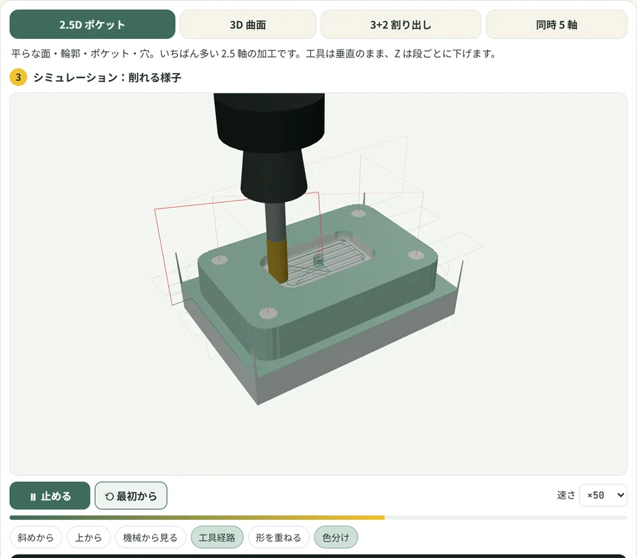 CAM experience (2.5-axis to simultaneous 5-axis)Choose a shape and a cutting method, and you get a toolpath and an NC program, then cut it on the spot
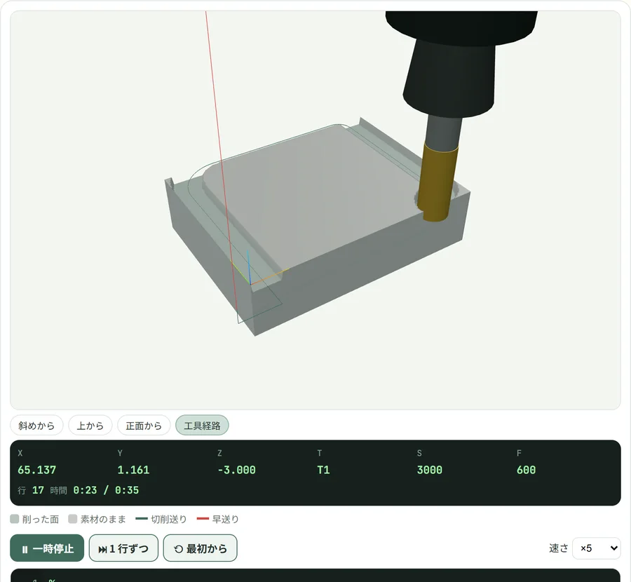 NC simulator for machining centersType G-code and run it to cut in 3D. Includes 5 practice problems
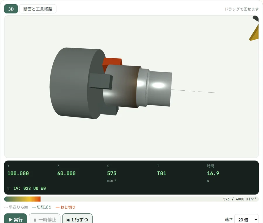 3D simulator for CNC lathesA mill-scale (black skin) bar is cut into steps, tapers and radii. Graded practice problems too
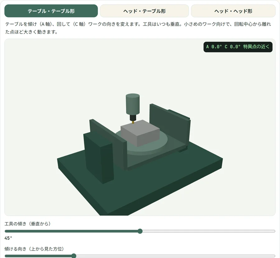 5-axis machine motionSee three machine configurations, with and without TCP, and the C axis spinning at a singularity
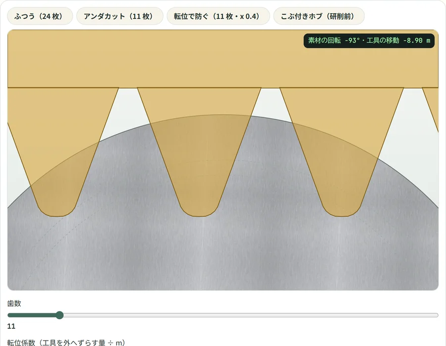 Gear meshing and generationContact point, contact ratio, backlash, and a hob cutting the teeth
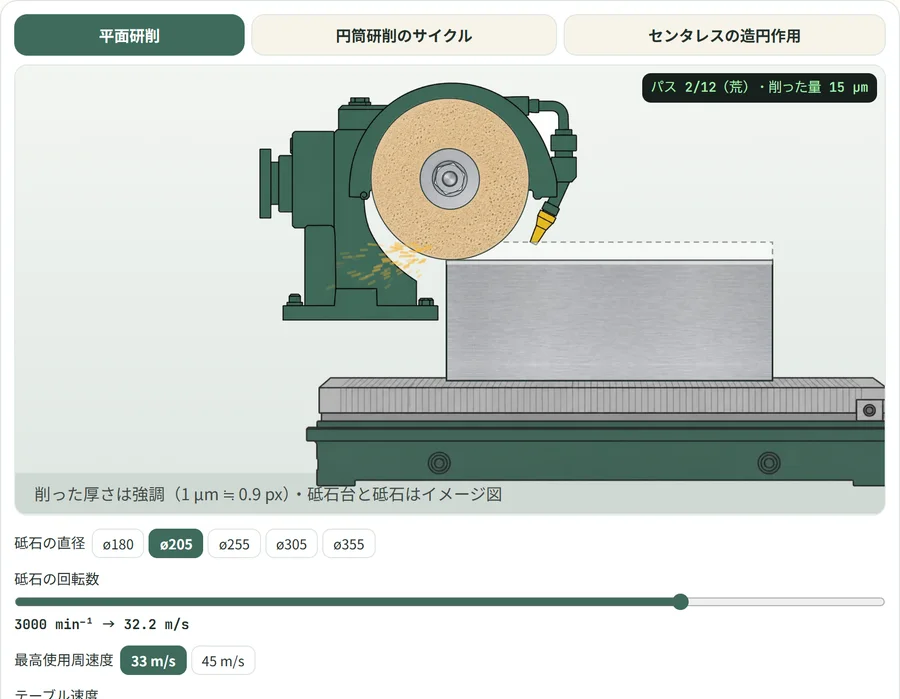 Grinders (surface, cylindrical, centerless)Depth of cut and grinding burn tendency, the cylindrical grinding cycle, and the centerless rounding effect
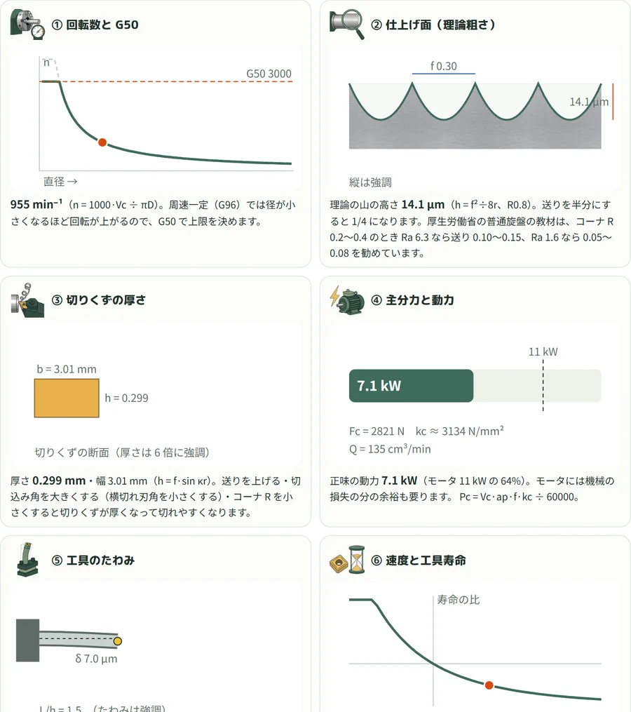 Turning conditions made visibleMove the feed and depth of cut, and spindle speed, surface roughness, power, deflection and tool life all change
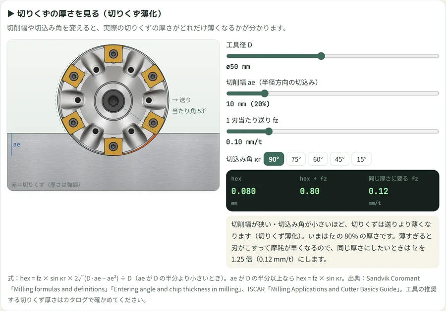 Chip thickness (chip thinning)A narrower width of cut makes thinner chips. It also shows the feed needed for the same thickness
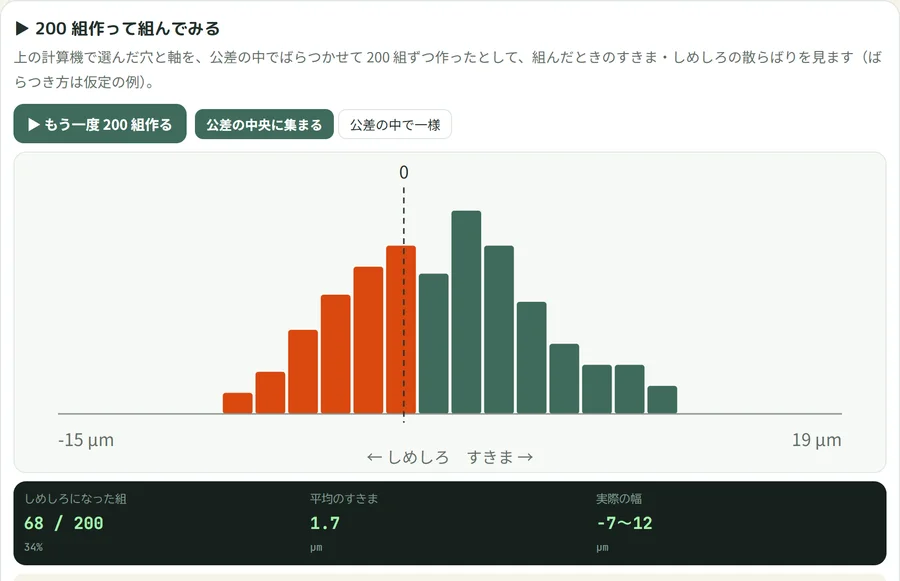 Build 200 fitsScatter parts within tolerance and see the share of interference and clearance fits
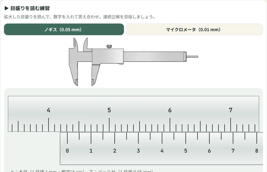 Scale-reading practiceRead caliper (0.05 mm) and micrometer (0.01 mm) scales and check your answer
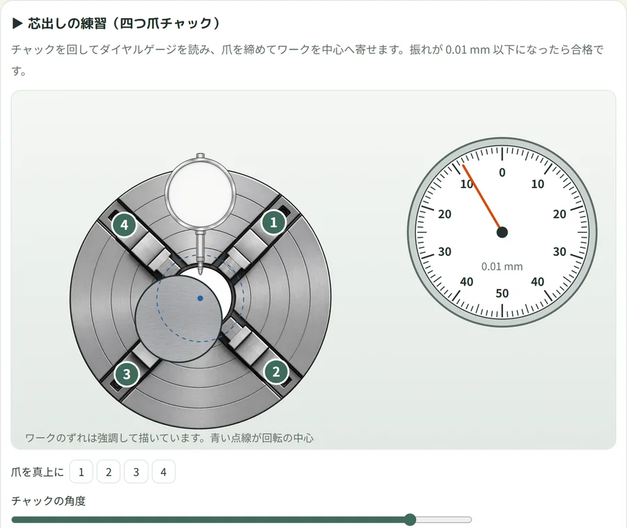 Centering practice (four-jaw chuck)Turn the chuck, read the dial indicator, and tighten the jaws to bring the runout down
Try one question right here. Below is the "Scale-reading practice" itself. Read the caliper scale, type in the number, and check your answer. The other 10 simulators work right on the page in the same way.
1. CAM experience (2.5-axis to simultaneous 5-axis)
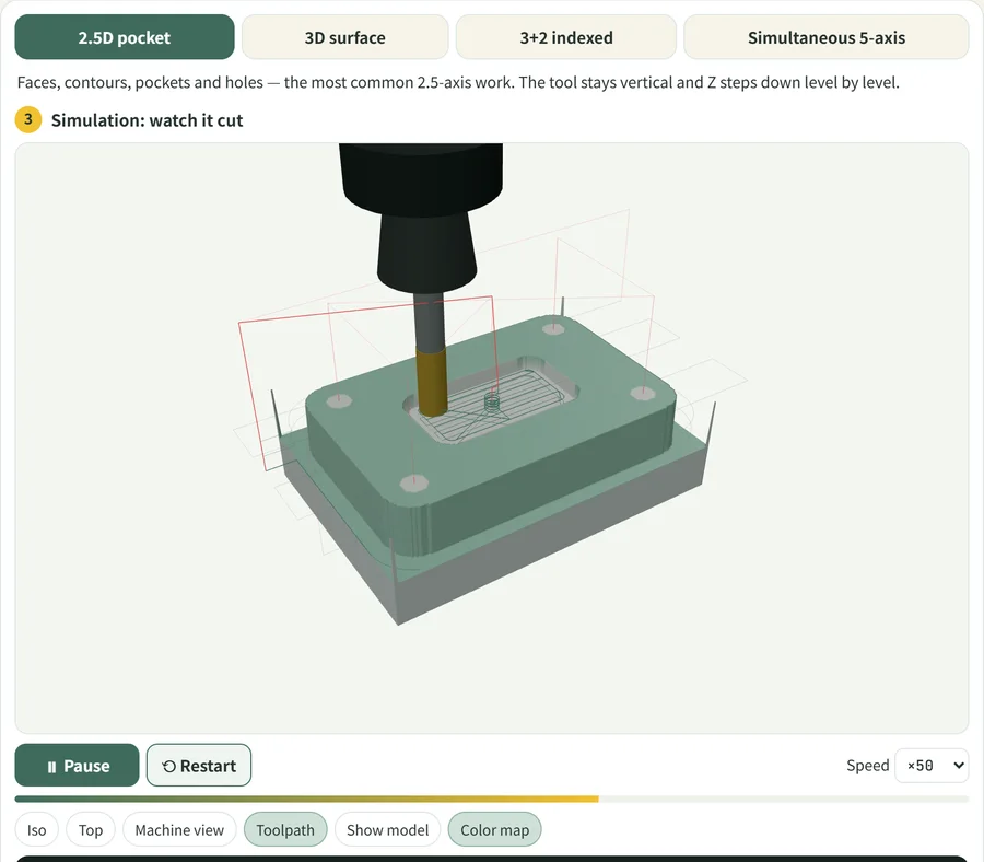
Decide the shape in CAD, then choose how to cut it in CAM (tool, depth of cut, stepover, cutting strategy), and you get a toolpath and an NC program, and can cut it in 3D on the spot. There are four kinds of machining: "2.5-axis pocket," "3D surface," "3+2 indexing" and "simultaneous 5-axis." For the post-processor (NC program output) you can choose FANUC or HEIDENHAIN format, and save the result as an .nc file. It also shows uncut and overcut areas in color, along with a machining-time estimate.
2. NC simulator for machining centers
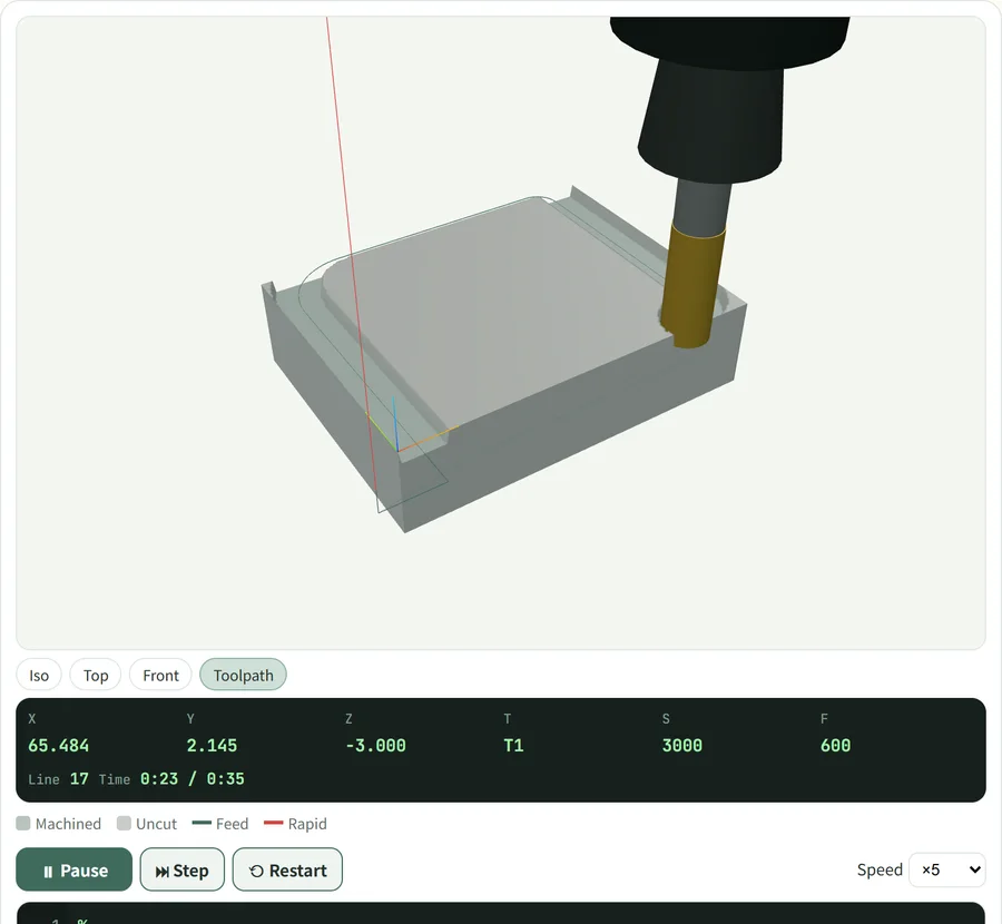
Type G-code into the editor and press Run, and the machining center cuts the stock in 3D. You can step through one line at a time, change the speed, and view from an angle, from above or from the front. It comes with 5 practice problems that judge whether the part was cut to the drawing, so you can learn G00, G01, G02/G03 and tool length compensation hands-on.
Open the machining simulator →
3. 3D simulator for CNC lathes
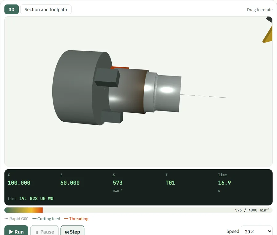
Type G-code following CNC lathe conventions (X is diameter, the origin is the center of the end face), and you can see a mill-scale round bar cut into steps, tapers and radii in 3D. You can also switch to a cross-section and toolpath view. The article "Introduction to CNC Lathe Programs" has 5 practice problems that automatically check whether the part was cut to the drawing, and you can send the program you wrote to others as a link.
Open the CNC lathe simulator →
4. 5-axis machine motion
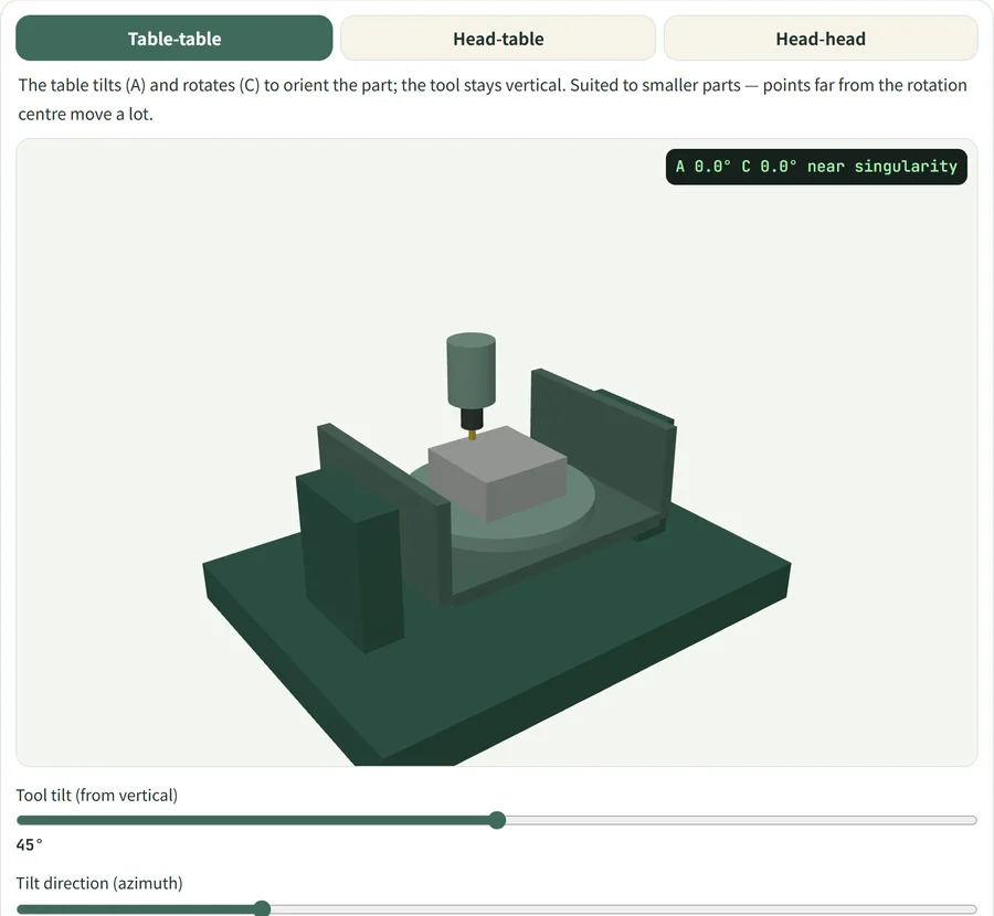
Switch between three machine configurations ("table-table," "head-table" and "head-head") to see which machine axes move, and how, when the tool tilts. You can also see the tool tip drift off when tool center point control (TCP) is turned off, and experience the C axis spinning all at once when the path passes near the top: a singularity.
5. Gear meshing and generation
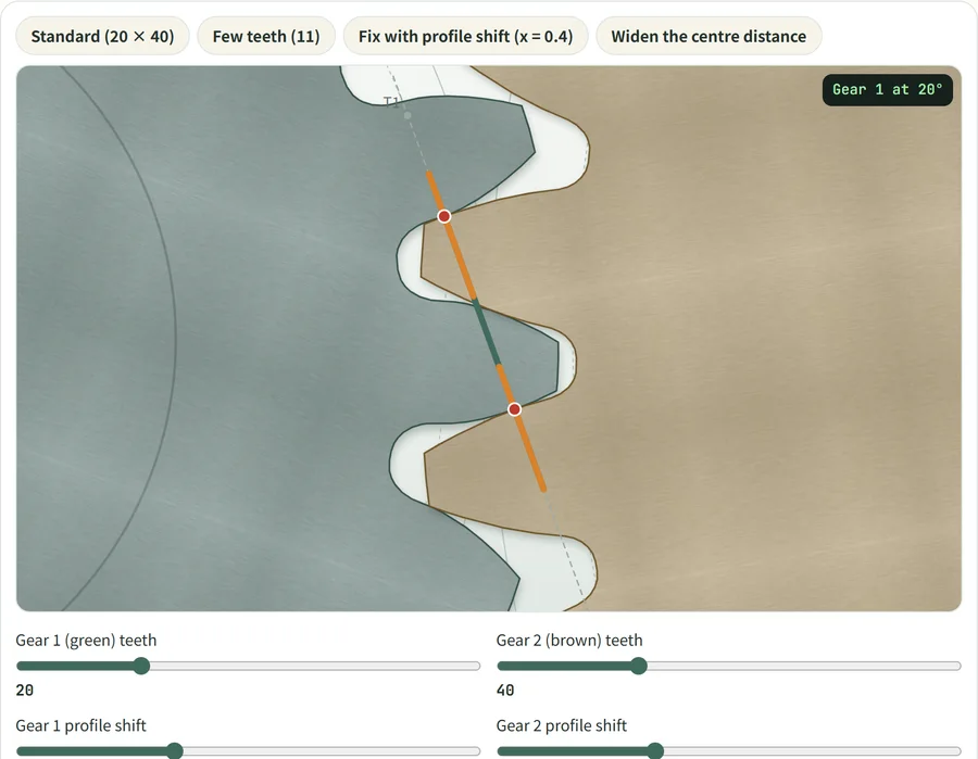
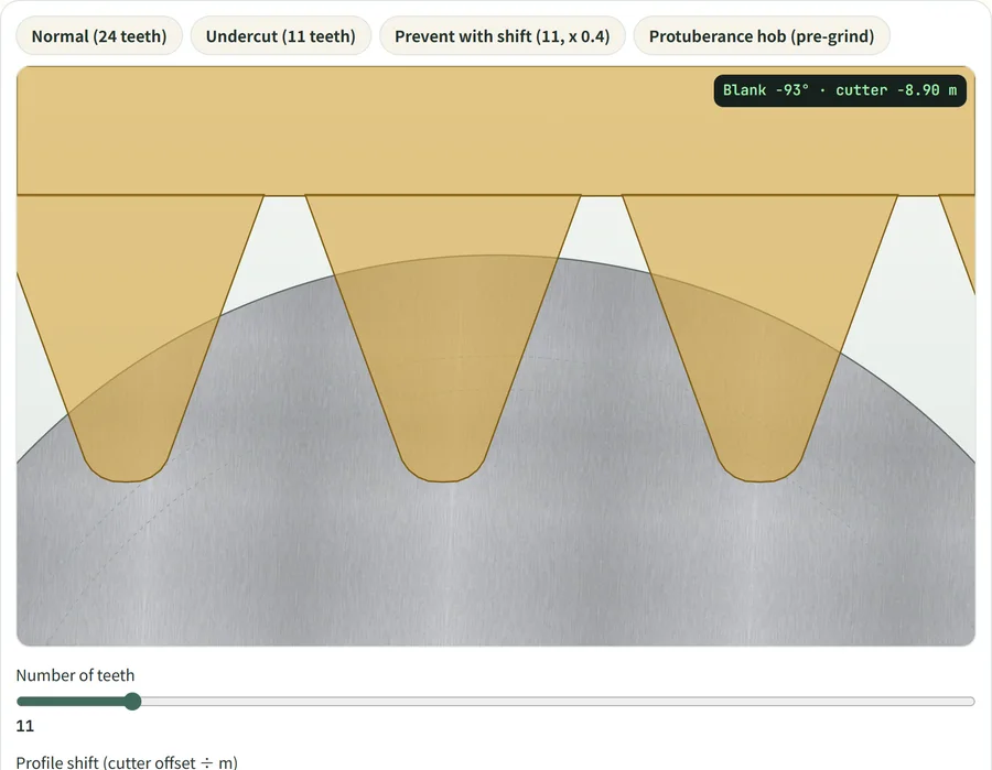
In meshing, change the number of teeth, profile shift coefficient, center distance, pressure angle and module to check contact point motion, contact ratio and backlash. In generation, you can watch the hob (a rack-shaped tool) cut out the teeth, see what happens when there are too few teeth (the tooth root gets gouged out, called undercut), how profile shift avoids it, and how a protuberance hob provides relief.
6. Grinders (surface, cylindrical, centerless)
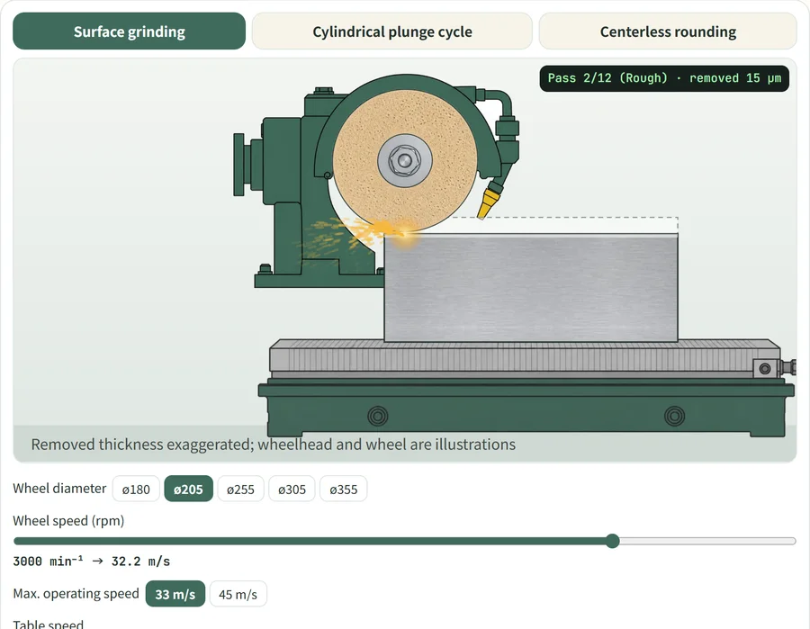
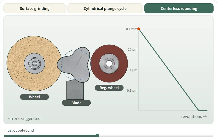
In surface grinding, see how burn susceptibility changes with conditions such as depth of cut and speed. In cylindrical grinding, you can see the rough grinding, fine grinding and spark-out cycle, and how deflection keeps the wheel from cutting as commanded. In centerless grinding, a workpiece supported at three points (grinding wheel, regulating wheel and work rest blade) gets rounder the more it turns (rounding effect), and you can check it with graphs.
7. Turning conditions made visible
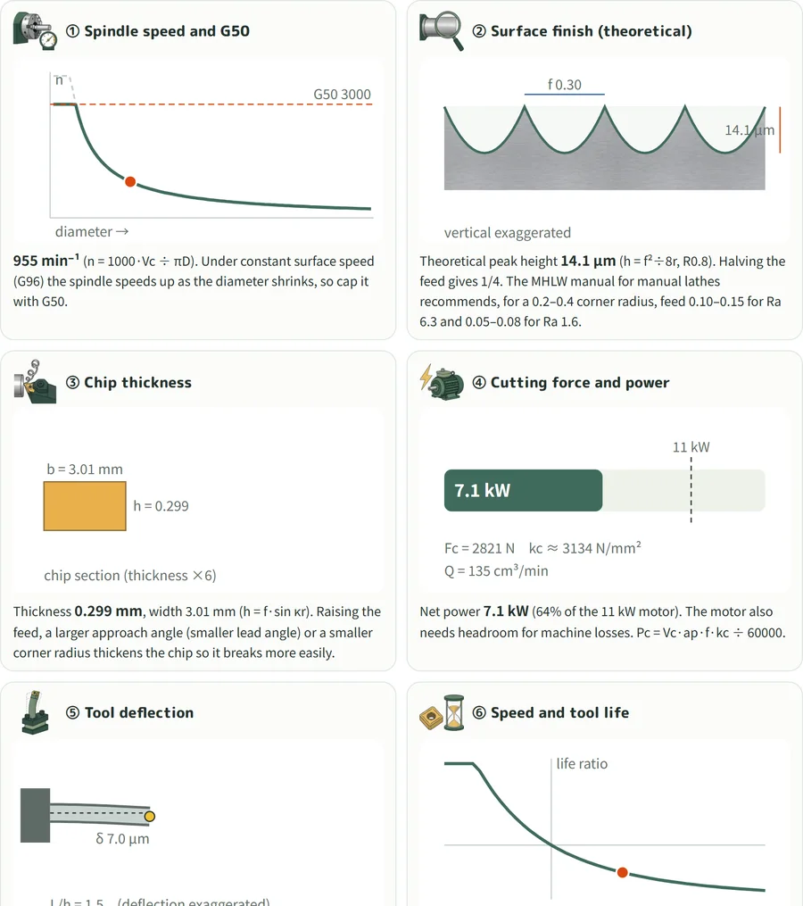
Change the workpiece material, cutting speed, feed, depth of cut, corner radius and tool overhang, and ① spindle speed and G50 ② finished surface (theoretical roughness) ③ chip thickness ④ main cutting force and power ⑤ tool deflection ⑥ speed and tool life — all six move together. Relationships like "raise the feed and the surface gets rougher" and "raise the depth of cut and you exceed the motor output" are clear at a glance.
8. Chip thickness (chip thinning)
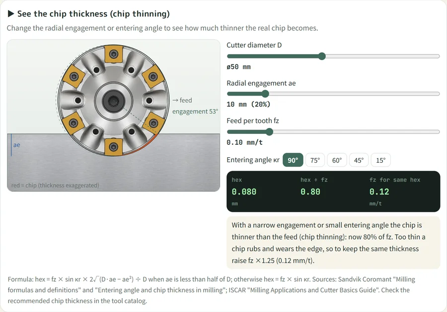
In milling, a narrower width of cut makes the chip thinner than the feed per tooth (chip thinning). Move the tool diameter, width of cut and entering angle, and you get the actual chip thickness and the feed needed to get the same thickness. It shows why you can raise the feed with light cuts.
9. Build 200 fits
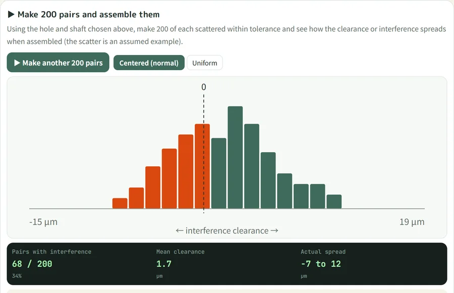
Take the hole and shaft you chose in the fits calculator, and scatter them within tolerance to make 200 pairs and see the distribution of clearance and interference once assembled. You can see that with a transition fit you "can't tell until you assemble," and how that differs from parts that cluster around the middle of the tolerance.
10. Scale-reading practice
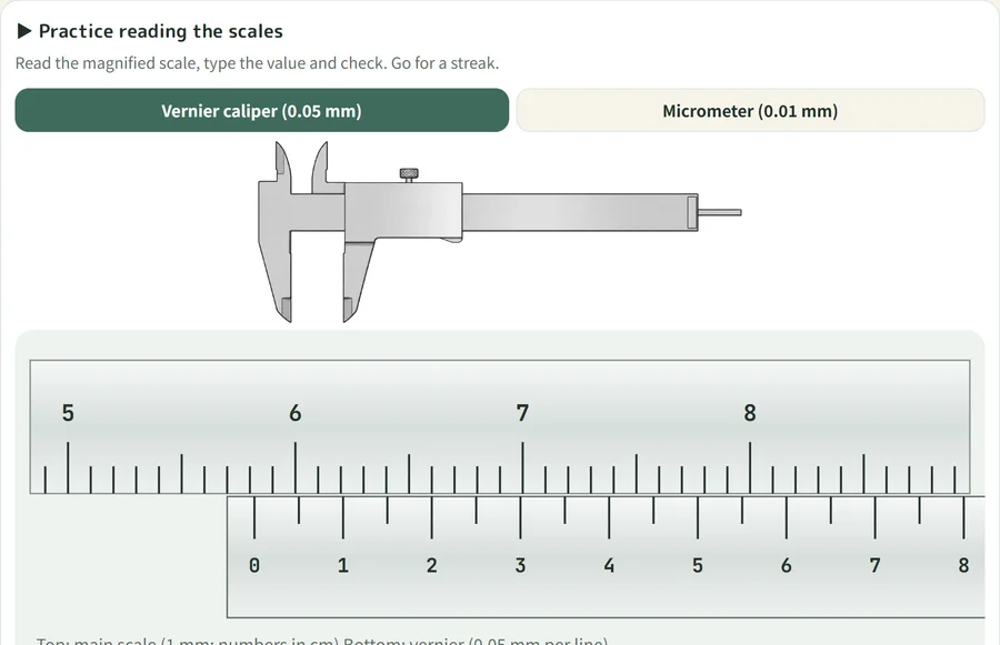
This is the same one you can try at the top of this article. The caliper (0.05 mm) and micrometer (0.01 mm) scales change every time, so you can read, enter, and check your answer again and again. It also shows your streak of correct answers.
Practice on the measuring tools page →
11. Centering practice (four-jaw chuck)
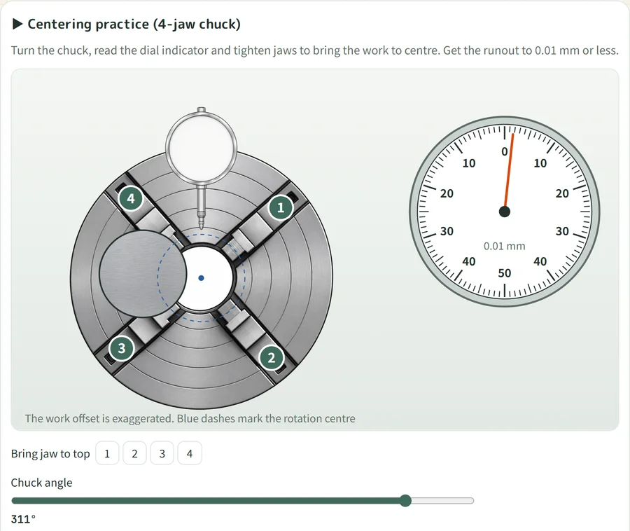
Turn a workpiece held in a four-jaw chuck, read the dial indicator, and tighten the jaws to move it to center. It's a practice exercise: get the runout to 0.01 mm or less to pass. It also counts how many tries you needed, so you can repeat it and learn the knack of "moving only half the runout."
Open the dial indicator centering →
Notes before you start
- All of them are simplified models for understanding the ideas. They differ from real machine motion, alarms and cutting conditions in places. Set real conditions from the tool manufacturer's recommendations and your machine's manual
- The 3D simulators may run slowly on older smartphones or in power-saving mode. If so, lower the speed or open them on a PC
- If you notice an error in a calculation or display, please let us know through Contact — it would be a big help
The entry point that gathers all the simulators is the Machining page. Short videos of them in action will also be shared on Kezuriba's X (@kezuribanet).
More articles
 Materials
Machining PEEK and Other Plastics: How They Differ from Metals, Cutting Conditions and Tools, Annealing, Dimensions and Plastic Gears
 Industry
Machining EV Parts: Parts That Shrink and Grow, eAxles and Battery Cases, Quiet Gears, Major Japanese Companies, Machine and Cutting Tools, New Technology, How to Enter
 Gauges